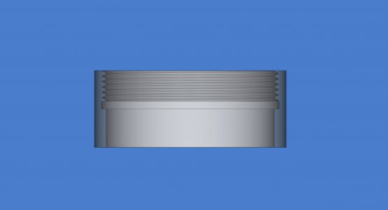
Can someone let me know how to get a dimensioned view of this tube end?

WobblyHand

H-M Supporter - Diamond Member
H-M Lifetime Diamond Member
Joined
Dec 18, 2019
Messages
6,448
Maybe I'm being dense (most likely!) but I'm having an issue with dimensioning the inside section of a tube. The tube has threads and a groove in it. For some reason, I can't even get any useful internal dimensions. Attached is the file. I was able to do the cap dimensioning without issue, but this tube is kicking my butt.
cf_tube_end.jpg
Issue is I can't seem to get a TechDraw view like the image above. None of the section views seem to be giving me what I'd expect. I tried a detail view and I can't seem to dimension from it. Can someone gently nudge me in the right direction? I want dimensions on my print to match up with my sketches, like groove dimensions and thread depth. They will just be a machining guide, to prevent me from making grievous screw ups in the shop.
 

Attachments

  • endcap.FCStd
    478.3 KB · Views: 7
I suspect you have quite a bit more FreeCAD experience than I do, but figured I'd take a look at it. Seems like a pretty logical view for internal threads.

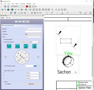
I haven't used TechDraw in v0.21 much yet, and haven't run into the newer section view functions in it. Looking at the below image, I started with the pipe in the "view" oriented as in your picture above. I selected the second of the turquoise section functions, arrows down. (I would expect the third or fourth turqouise buttons to give you the desired section view, but got nothing meaningful). Then I used the "View Direction as Angle" and changed the angle a few degrees at a time, from 270 to 231 and hit the "Update Now" at the bottom as I went. That gave me the image below.

Based on this, it looks to me like the 3D view for the perspective in this section view is from a section plane that does not intersect the pipe, but rather is from outside the pipe and therefore doesn't render the interior. I tried to play with the X/Y/Z section plane location to see if I could bring it to the interior of the pipe. Once those values go into something illegal, the section view goes blank, and restoring the previously working values doesn't restore the previous view. At that point, I had to delete and recreate the section view to get back to anything. I'm guessing that the right combination of "Current View Direction" and "Section Plane Location" would make it work, but with the issue of it melting down on a bad section plane location, it was too tedious to try to find appropriate values.

So in short, can't help. I'd say you need to query the FreeCad forums at this point?

section.jpg
 
Last edited:
Note that to get the "Insert Simple or Complex Section View" icon to work in TechDraw, I had to double click the "CFTubeBody" to make it active before it would allow me to use the section view tool. That created a "Section" in the page model tree rather than another view. That's the function that I expect, from V0.20, to give a cut-away view. I think that's what you're looking for?
 
Last edited:
I haven't used TechDraw in v0.21 much yet, and haven't run into the newer section view functions in it. Looking at the below image, I started with the pipe in the "view" oriented as in your picture above. I selected the second of the turquoise section functions, arrows down. Then I used the "View Direction as Angle" and changed the angle a few degrees at a time, from 270 to 231 and hit the "Update Now" at the bottom as I went.

Based on this, it looks to me like the 3D view for the perspective in this section view is from a section plane that does not intersect the pipe, but rather is from outside the pipe and doesn't render the interior. I tried to play with the X/Y/Z section plane location to see if I could bring it to the interior of the pipe. Once those values go into something illegal, the section view goes blank, and restoring the previously working values doesn't restore the previous view. At that point, I had to delete and recreate the section view to get back to anything.

So in short, can't help. I'd say you need to query the FreeCad forums at this point?

View attachment 460602
Well, at least it isn't me being dense. I think something is broken (again). There's been issues that I have noted that using the navigator cube doesn't always end up at orthogonal values, which effs up views and or dimensions. I tried to inquire about that, but they insist it's ok. I think they have some sort of math error there, as I have had it burn me a few times.

Played with it some more, doesn't seem to work as it used to. Dunno, maybe they changed the name to complex section view?
 
Nope. I'm going to do a git pull and rebuild. I am on the dev version, so maybe it's a bug that has been fixed already. It will take about 5 minutes or so to rebuild. Worth a try. If that doesn't work, then off to their forum.
 
Using pseudo threads the section view works. However, a true thread formed from a subtractive helix fails to render properly.

However the male thread renders at least on a non section view. Wonder if a section of the male end cap would work.

I did post on the FreeCAD forum, but haven't seen a response yet. Interesting problem, too bad it's mine ;)
 
Actually it's more complicated. Definitely a bug. It will render threads in section view under some circumstances. If there is an intersecting groove, think thread gutter, well, it screws up in the very condition that we are interested in. Having a thread gutter intersect the end of the thread? Forget about it. I can watch it render or not render depending on the height of the groove. The critical region is where the helix ends. If the groove is near there the section view fails. If the groove is in the middle of the threads, no problem. If the groove is "far" from the thread end, no problem. If the groove is at the start of the threads, no problem.

For what it is worth,, this bug is present in 0.20.2 AppImage as well. And 0.21, and 0.22dev.
 
That is consistent with what I was encountering when rotating the model via the section view dialogue.
Does it matter if the threads or the gutter are first in the model tree?

Regardless, I'll be interested in hearing what you find out from the forums, etc.
 
That is consistent with what I was encountering when rotating the model via the section view dialogue.
Does it matter if the threads or the gutter are first in the model tree?

Regardless, I'll be interested in hearing what you find out from the forums, etc.
No idea. In my example file (made this morning) the helix was first, then the groove to cover it up. Varying the groove height made the section view work, or not.

Also found out that the macro EasyAlias doesn't work any more for 0.22dev. That's the macro that lets you make parameterized designs easily using spreadsheets. Spreadsheets are useless without the macro...

So far no response on the FreeCAD forum - seems to be quiet there today.
 
Nope, doesn't matter if the groove is made first, then the helix. Nor where the helix starts... Same error, basically a silent fail to render the section view properly.
 
Back
Top