-
Welcome back Guest! Did you know you can mentor other members here at H-M? If not, please check out our Relaunch of Hobby Machinist Mentoring Program!
You are using an out of date browser. It may not display this or other websites correctly.
You should upgrade or use an alternative browser.
You should upgrade or use an alternative browser.
capacitor on motor smashed!!
- Thread starter pjf134
- Start date
- Joined
- Sep 22, 2010
- Messages
- 898
Paul
It is going to depend on how many of the leads were brough out to the wiring junction box as to whether you can revese the motor or not.
IF the motor was wired in such a way that it was considered non reversible, that means that some of the wires are wired directly to the motor windings. These motors are reversible at a cost, they require surgery to open up the crown and draw out the extra wires. I did this for Baldor when they had mis-ordered a bathc of motors for a compressor plant. The motors were all rotating the wrong way, so I was contracted to switch them all around.
A conventional reversible motor will have between four and six leads in the junction box, depending on Voltage.
110 Volt only motor, four leads
110/220 Volt motor six leads
each set of leads is 110 Volts. Two sets will be run windings, and the other set will be the start winding.
We will deal with the dual voltage reversible motor here.
to wire the motor for 110V, all three sets of leads will be wired in parallel.
to wire the motor for 220V the two run windings will be in series and the start winding will be in parallel to ONE of the run windings.
To reverse the rotation, interchange the two start windings leads, usually tagged as 5 and 8 or in ChuckB's case as red and yellow.
A three phase motor is reversibel even easier, just swap any two power lines and presto chango, it now turns the other way.
If you have any further questions, post some more pictures and we will attempt to get you so confused your head will never stop spinning, LOL OK so may we will just try to get the fan spinning and not the head.
Walter
- Joined
- Jan 2, 2011
- Messages
- 331
Yes, if you can find the start winding, identified as the winding that has the cap and the centrifigal switch in series then by reversing it, it will change the direction of the motor. Very easy to do with an ohm meter as long as it is already isolated. Otherwise you will have to cut some wires to even identify the starter circuit.. kind of a guessing game.
- Joined
- Jan 26, 2011
- Messages
- 632
- Joined
- Jan 2, 2011
- Messages
- 331
Wow.. I don't think I can be much help with that, unless I was your next door neighbor.. 
Are you electrically inclined and good with a meter?
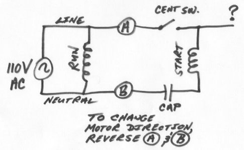
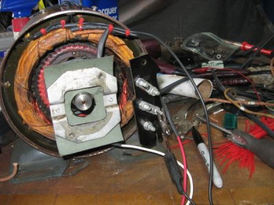
It looks as though your start winding is isolated, but it's a matter of finding it.. I was in a similiar situation with my motor. Some colors had faded, so I had to take my motor apart and trace it with an ohm meter, thus the basic drawing that I posted. The one wire with the question mark in my drawing was not used.. apparently someone added it to monitor the full motor speed (when the centrifigal switch kicked out.) I'm glad I opened mine up though, all the wiring was cracked and I repaired it with new wiring and heat shrink.

- Joined
- Jan 2, 2011
- Messages
- 331
[quote author=Tony Wells link=topic=1587.msg9480#msg9480 date=1302365600]
Hahaha! Great, Chuck! Not many people would trouble themselves even to attempt that.
[/quote]
I was just trying to get the customers door back in service and keep my boss happy. It was also fun showing off to the in house maintenance crew as to what I could do in a pinch.
Hahaha! Great, Chuck! Not many people would trouble themselves even to attempt that.
[/quote]
I was just trying to get the customers door back in service and keep my boss happy. It was also fun showing off to the in house maintenance crew as to what I could do in a pinch.
- Joined
- Jan 26, 2011
- Messages
- 632
Chuck,
I do have meters and have done some electric work, mainly working with one of my friends who does that type of work. I used to do scoreboards with him when he needed an extra hand, also other types of electric. He is working 16 hour days now,so he is not my go to guy right now. I can use a meter if you just tell me in layman terms what to hook too, such as ohm reading from L1 to L2 ect. I really have not messed with motors that much so do not know the lingo.
Thanks,
Paul
- Joined
- Jan 2, 2011
- Messages
- 331
Paul, Here goes..I will try to explain this the best I can.. I am no engineer, but am quite good at figuring some things out. I include this as one of those things. This is exactly what I did, and it worked for me. Anyone that wants to explain it better, feel free to do so.. ;D
Look at my basic circuit. You will observe that it is really two circuits in one. One to the left of "A" and "B" and one to the right of "A" and "B". If you can't comprehend this, stop now and get help.
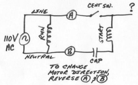
The run circuit has more windings than shown in my drawing, but when isolating the run windings for the start winding, lets keep things simple and treat the run circuit as one winding. Getting more involved with the run windings will occur if you are changing to 220 volts, which will not affect the start winding.
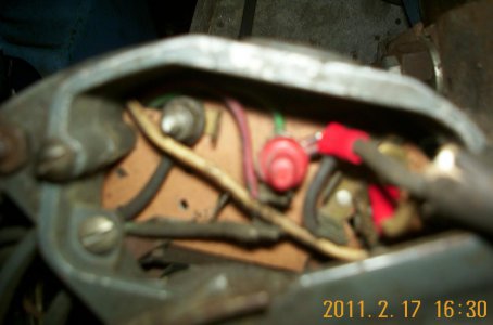
The first thing I would do is mark all the wires using a wire marker kit or some other means.Get your camera out and take many close up pictures too. They will help if you get in trouble. I would remove all the wiring from in front of the terminal plate. If it's within your capabilities, I would remove the motor housing cover,(If removing this housing is not within your capabilities, stop and get some help.) Make sure to unscrew the centrifugal switch first, then the long screws with nuts come out. Although somtimes, difficult, the housing will come off with a little coaxing. Make sure you don't lose any of the bearing shims. also remove the two screws in the back of the terminal plate. You now can then get to the centrifugal switch that connects to the capacitor and looking at my diagram be able to isolate the start winding.. again, the start winding will be the one that has the capacitor and the centrifugal switch in series with it.. This circuit should be seperate and have no relation to the wires on the back of the terminal plate.There are probably four wires in the rear of the plate and these are the run windings. (see picture below of the multi colored wires connected to the back of the terminal plate.)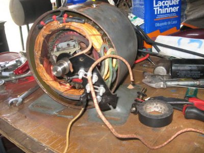
In some instances, as Walter mentioned the start winding wires will be connected directly to the run winding wires and will have to be isolated. When you are done you will end up with four wires, which are the two above mentioned circuits. By reversing the two start winding wires, the motor will reverse.
When putting the motor housing back on, make sure no wires are rubbing and also make sure the motor spins freely..as freely as it did before you took it apart.
Now you can try and get lucky by not taking the motor apart and just guessing, but this is how I recommend to do it.. It's your choice.
This is the best way I can explain this without having your motor in front of me.. probably the hard way, but it is the sure way..
Again, this is the exact way I figured mine out. I hope this helps a little. Maybe others can chime in for some additional support.
EDIT------------------------------------------------------
I might add that the capacitor, centrifugal switch and start winding doesn't necessarily have to be in the order of my drawing to work. As long as they are in series. I have saw different variations.
Look at my basic circuit. You will observe that it is really two circuits in one. One to the left of "A" and "B" and one to the right of "A" and "B". If you can't comprehend this, stop now and get help.

The run circuit has more windings than shown in my drawing, but when isolating the run windings for the start winding, lets keep things simple and treat the run circuit as one winding. Getting more involved with the run windings will occur if you are changing to 220 volts, which will not affect the start winding.
The first thing I would do is mark all the wires using a wire marker kit or some other means.Get your camera out and take many close up pictures too. They will help if you get in trouble. I would remove all the wiring from in front of the terminal plate. If it's within your capabilities, I would remove the motor housing cover,(If removing this housing is not within your capabilities, stop and get some help.) Make sure to unscrew the centrifugal switch first, then the long screws with nuts come out. Although somtimes, difficult, the housing will come off with a little coaxing. Make sure you don't lose any of the bearing shims. also remove the two screws in the back of the terminal plate. You now can then get to the centrifugal switch that connects to the capacitor and looking at my diagram be able to isolate the start winding.. again, the start winding will be the one that has the capacitor and the centrifugal switch in series with it.. This circuit should be seperate and have no relation to the wires on the back of the terminal plate.There are probably four wires in the rear of the plate and these are the run windings. (see picture below of the multi colored wires connected to the back of the terminal plate.)

In some instances, as Walter mentioned the start winding wires will be connected directly to the run winding wires and will have to be isolated. When you are done you will end up with four wires, which are the two above mentioned circuits. By reversing the two start winding wires, the motor will reverse.
When putting the motor housing back on, make sure no wires are rubbing and also make sure the motor spins freely..as freely as it did before you took it apart.
Now you can try and get lucky by not taking the motor apart and just guessing, but this is how I recommend to do it.. It's your choice.
This is the best way I can explain this without having your motor in front of me.. probably the hard way, but it is the sure way..
Again, this is the exact way I figured mine out. I hope this helps a little. Maybe others can chime in for some additional support.
EDIT------------------------------------------------------
I might add that the capacitor, centrifugal switch and start winding doesn't necessarily have to be in the order of my drawing to work. As long as they are in series. I have saw different variations.
- Joined
- Sep 22, 2010
- Messages
- 898
Paul
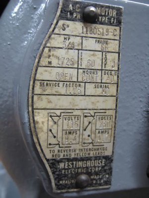
your motor is dual voltage so you will have two run windings in parallel to each other when wired 110V, not just one as shown in ChuckB's diagram
Walter
your motor is dual voltage so you will have two run windings in parallel to each other when wired 110V, not just one as shown in ChuckB's diagram
Walter
- Joined
- Jan 2, 2011
- Messages
- 331
[quote author=starlight_tools link=topic=1587.msg9554#msg9554 date=1302415044]
Paul
your motor is dual voltage so you will have two run windings in parallel to each other when wired 110V, not just one as shown in ChuckB's diagram
Walter
[/quote]
Walter re-read my post.. I covered that point:
"The run circuit has more windings than shown in my drawing, but when isolating the run windings from the start winding, lets keep things simple and treat the run circuit as one winding. Getting more involved with the run windings will occur if you are changing to 220 volts, which will not affect the start winding."
He is asking how to reverse his motor by finding and isolating the start windings, not how to change the motor to 220.. I would think that he wouldn't have to touch the run windings.
Let's don't make this more confusing than it has to be for him..


