Card Press

tcarrington

Making miscellaneous parts for years now
H-M Platinum Supporter
Joined
Dec 27, 2013
Messages
124
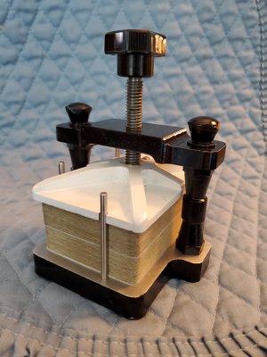
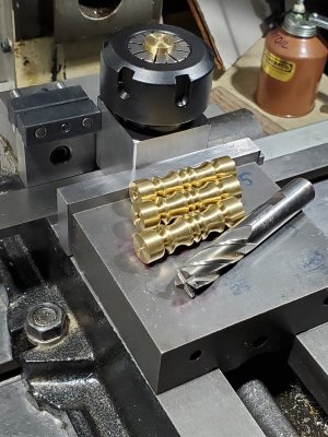
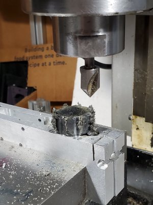
This thread is a build for a card press, bridge or playing. Inspired by ClickSpring's opus for Chris Ramsey. Don't judge. These are in no way as pretty, nor is the craftsmanship comparable. No snakes were harmed in this build either.

PROCESS
Wanted something that was not difficult or overly ornate when built. In many ways, I realized this was a lot like buggy whips - who uses cards now? Largely confined to bridge and poker players at live events, I think.
 
PROTOTYPE
Had some scrap aluminum to try it out and see what it looked like in the end and to have a basis upon which improvement or just stylistic changes would be more easily viisualized. This part was probably worth it. Better paint job might enhance it and changing the SHCS to a smaller, stealthier retaining pin would be a good thing to do.
Learned how to plug exising holes in the base and the presser plate. That alone was worth the experience. The base and presser plate had a couple of small holes that I could not work around, so they have to be plugged.
This is one is for bridge sized cards and will accomodate two decks, as many cards come in two deck sets and most people use two decks to streamline play.
The prototype also cemented the idea of a turned down SS nut for the lead screw. It also proved that I wanted to turn the lead screw to fit the nut just a little bit better. Used materials at hand. Sticky felt pads for feet let it coexist on a wood table. Six were used to protect the corners and middle.
 

Attachments

  • 01_Prototype.jpg
    01_Prototype.jpg
    1.4 MB · Views: 29
FIRST UNIT
Sounds like this is going to production, but no way. Made two sets of parts which was especially useful for the cross bar. This is where style became apparent. The bars were cut to lenth and the ends finished with the 0.500 dia features with a 0.125 diameter hole in the middle. This allowed the two parts to be repeatibly joined for many of the operations.
 

Attachments

  • 02_CrossBar.jpg
    02_CrossBar.jpg
    2.5 MB · Views: 28
One tricky part was positioning and cutting the angle on the top of the cross bar. The part and a fixing plate were pressure clamped to the lathe face plate and driven by a dog attached to the face plate.
The angle was walked in by adjusting the compound to get a good diameter looking feature on the top in the middle and a blend on the outside ends. This feature was more artistic and less functional.
 

Attachments

  • 03_CrossBarAngle.jpg
    03_CrossBarAngle.jpg
    2 MB · Views: 19
Similarly the upright supports, while a little out of place stylistically were interesting. First, a good plan needed to make four of something. Even a drawing would help. Ground a form tool with the right radius for the two larger features. the smaller features were made with the HSS threading tool.

Here is where you want a smart son, who is a machinist. He gave me an ER32 collet set for Christmas and it was extremely helpful. The uprights are exactly the right length to be captured on both ends in the ER32 collet. This made second operation on four pieces go like butter on a muffin. The part-off surface was improved, and a 10-32 thread was accomplished on the other end. Overall lengths were matched.
 

Attachments

  • 04_Upright.jpg
    04_Upright.jpg
    1.8 MB · Views: 16
  • 05_UprightCollet.jpg
    05_UprightCollet.jpg
    1.4 MB · Views: 14
The presser plate was made from two pieces, soldered. This saves material and allows the 8-32 hole for the retaining pin to be easily accomplished. The plate has the three notches to engage the dowel pins to prevent rotation. The dowel pins also provide the needed function for aligning the cards and preventing their sliding out.
 

Attachments

  • 06_PresserPlate.jpg
    06_PresserPlate.jpg
    2 MB · Views: 13
  • 07_PresserSolder.jpg
    07_PresserSolder.jpg
    2.6 MB · Views: 13
The leadscrew is stainless, 3/8-16 turned to fit the commercial nuts which were turned down and inserted into the crossbar. This improved the usual 2B/2A standard tolerance fit.

A cross hole was made for 0.125 diameter dowel pins to fix the knob.
 

Attachments

  • 08_LeadScrew.jpg
    08_LeadScrew.jpg
    1.2 MB · Views: 14
The prototype used a modified commercial clamp knob. Fast and inexpensive. I had several of these to repair microphone stands. The brass version has a custom knob. Eight flutes. Why not? This means a lot of machining time. By the time they were finished there were only slightly more functional. The knob is 1 inch nylatron turned and milled with a 0.25 diameter end mill to create the facets / flutes. Followed up with a generous counter sink and a second trip on the lathe to clean up and match the chamfers.
 

Attachments

  • 09_Knob.jpg
    09_Knob.jpg
    1.3 MB · Views: 12
Lacking other inspiration, two small brass knobs (0.620 diameter) were fabricated similar to the larger nylatron knob. These fix the cross bar to the uprights. A short piece of SS 10-32 was retained in the brass knob with thread locker. The end of the all thread in the knob was tapered similar to that of the tap used to create the thread in the knob. This, in my opinion, makes it better by providing more surface for engagement and thread locker.
 

Attachments

  • 10_SmallKnobs.jpg
    10_SmallKnobs.jpg
    1.1 MB · Views: 13
Threaded a brass rod (SS would probably be better) with a dog to fit the lead screw to affix the presser plate to the lead screw. The lead screw has a groove to accept the dog.

The brass spacer. shim, wear plate covers the ugly end of the lead screw and lessens wear to the presser plate. A bit of lubricant went into the hole on the presser plate and on the surfaces of the spacer.
 

Attachments

  • 11_AllPieces.jpg
    11_AllPieces.jpg
    1.5 MB · Views: 13
  • 12_FancyPieces.jpg
    12_FancyPieces.jpg
    2.6 MB · Views: 13
  • 13_SmallerPieces.jpg
    13_SmallerPieces.jpg
    2.4 MB · Views: 24
Back
Top