F
Firestopper
Forum Guest
Register Today
I recently purchased this unit sight unseen from the City of Gilbert AZ. I went through Public Auctions for the bid process and after a little bid war with what appeared to be a pawn shop (based on the bidders handle) I was high bid at $1586.xx after taxes and processing fee. There was four photos (poor quality) along with the auction so kinda limited on my end. This model is BPO 614-6 with a Serial No. 316138. I found out from Dreis&Krump that the machine was sold to the USAF back in 1977. Its a 6ft (73") unit with a max bending capacity of 14 gauge mild steel across the entire 73". I doubt I will ever need to build a box that long so I could be able to fold thicker narrower sections including aluminum. Now for the risks on buying a brake sight unseen: Many knuckleheads will bend/brake items such as round bar and thick flat strap using cheaters for leverage. This poor practice can result in a "sprung" condition ruining a brake, or damaging Nose bars and hardened bottom bars as well as bending bars. This model is a BPO, "O"meaning optional bolt on hardened bars. Thats a good thing considering the other BP models have welded bars. The bottom bar has the ability to be flipped (like shear blades) to expose a virgin side. All the dings on worn bars transfer to the bends on softer material such as aluminum once clamped. The same goes for damaged Nose bars.The Nose bars can be reworked on a mill (I'm hoping) and the finger extensions can be made from 3/4" thick CR flat bar on a mill and vary in different widths (3",4",5"and 6") determined by the width of the Nose bar. These can also be "sprung" when abused. At first I was under the impression I was missing one finger, but after receiving literature from Dreis, I was pleased to find the machines complete.
I made the 130+ mile drive after shift to pick up the unit only to find the forklift operator forked it from the upper clamp to remove the machine from inside storage. This is not advisable and could damage the unit. I had loaded any rigging equipment I thought might be need to load the machine onto a 14K dump trailer I was pulling (little tall).
After removing all the fingers to lighten/balance the pick, I rigged it for picking and that went smooth. Secured the load for my 130+ mile drive home. I used every strap I keep in the rig.
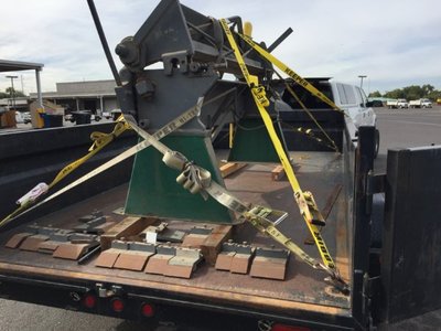
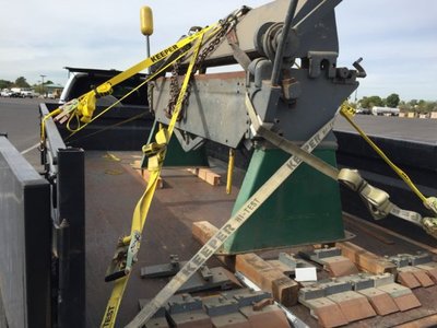
I got home around 2:30 pm and backed in the trailer for the night. I was too tired to unload the unit as I had worked a 24 hour shift that kept us up pretty much all night at explosion/fire that required 4,000 GPM and fifty firefighters. I had it made compared to the guys on the ground handling 2.5" hand lines. It was a defensive fire and we had exposures to protect. I was up 110' operating a Master stream from bucket ladder truck with onboard air (no SCBA required) plugged into my face mask . I was pushing 800 GPM from the toggle switch controlling the nozzle so a cake walk compare to the young bucks on the ground. The explosion took place at a Jajoba processing plant that operated 24/7. http://www.tucsonnewsnow.com/story/36802022/5-hospitalized-after-building-explosion-fire. We did have a substantial amount of transmission lines to avoid as there was a power substation in close proximity. I could feel/hear the energy coming off those lines..Creepy feeling. Perhaps all in my head, who knows.
Anyway, back to the brake,
Unloading the machine from the bottom: I had place some 4"cribbing under the brake running perpendicular to the trailer stringer running parallel to the heavy load at the time of loading. I also didn't want the machine to slide on the metal deck incase of emergency braking. This proved to be very helpful when I unloaded alone. I was able to use 8' fork extensions made some years ago from 6" channel. I was able to approach from the end but needed to drag the unit closer to the end of trailer. This thing is top heavy and off CG as the top clamp section was dislodge when the guy forked it from the bottom portion of the top clamp. The unit wanted to rotate counter clockwise co large C-clamps secured the lower stand to the forks as well as a rigging chain to assist in pulling the machine closer to the trailers a$$ end.
Lifting and gently pulling machine to trailers edge allowing the 8' forks to capture the front stand.
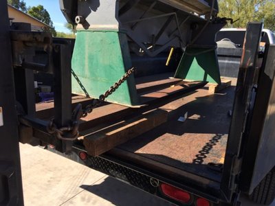
Got it on the ground without drama.
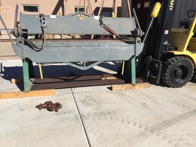
Next up was to reseat the upper clamp back onto the adjusting saddles.
I cribbed the unit leaving the fork extensions in place, then got a shorter 2X4 to use as a spacer under the upper clamp and gently raised the upper clamp to clear the saddle. I then raised the clamp arms using the cam action to line up the saddles and lowered the clamp into position. This went very easy and smooth.
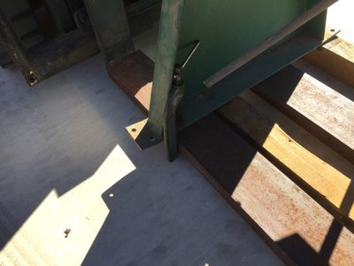
Here you can see the misalignment of the adjuster. Luckily the connecting threaded rod is robust at 2" and supported the knucklehead poor choice of method to move out the machine. Before I reseated, I took the adjuster apart to clean the hard dried grease making it hard to turn. This was put back dry for now and moves freely.
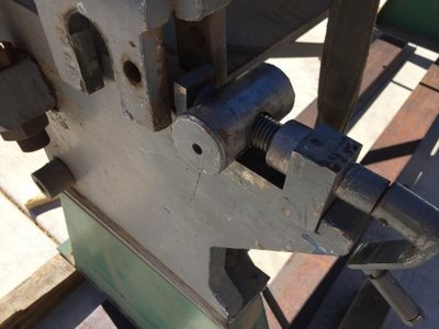
Short section of 2x4 to clear the finger extension mounts under the upper clamp.
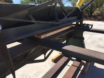
Raised it up just enough to rotate the cam lever to align the mouse hole over the L/R adjuster.
Once aligned, I gently lowered the upper clam to its home location. You can see the large clamp
adjustment threaded rod that connects the upper clamp to the lower portion of the table. The robust
design saved the brake from a total failed forklift pick. The sides are 1" thick plates as is the top end plates.
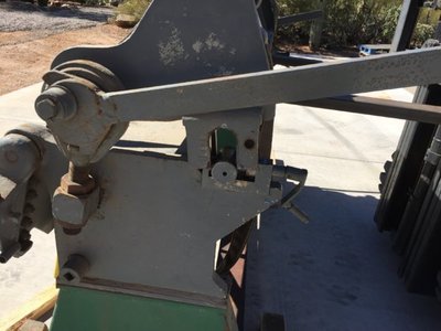
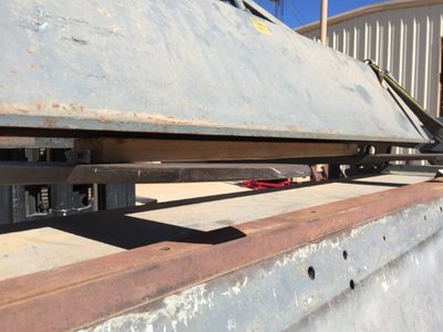
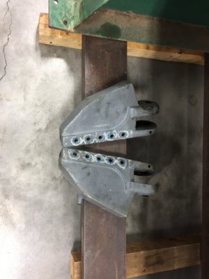
Here you can see the machined bar that supports the finger extensions (behind the 2x4). The
2x4 prevented fork contact during lifting of top clamp. Also notice the table and bending leaf hardened
Bar. The machine will require a bending angle bar to bend to capacity. A common piece of 1/4"x2" angle should
do the trick so long as its straight.
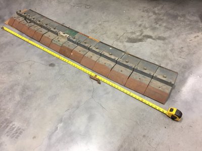
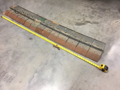
A total of 15 fingers and one custom made. I still need to inspect for damage, but right off the bat
they will beed to have the bottoms reconditioned. I also noticed one with damage from bending rod
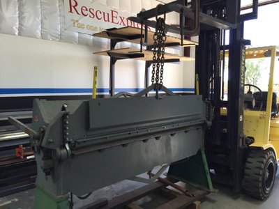
Spent a full day trying to adjust but found myself removing hardware to clean multiple coats of paint.
I also removed the table hardened bar to flip, the back side a virgin. The problem is two or three holes where drilled at the factory slightly misaligned. I should be able to slot them slightly using a mag drill. I was unsuccessful in aligning the leaf to the table by .0858". I decided to further tear down the folding leaf and inspect the pivot point for excessive wear that could be preventing the realignment. Working alone takes creative thinking at times when picking heavy items that want to rotate such as the leaf. I rotated the leaf 180º and secured a rigging chain and took up slack, then removed the two counter weight prior to removing the ten bolts.
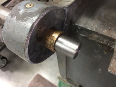
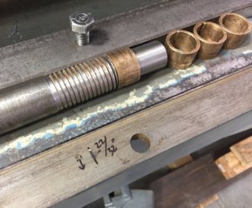
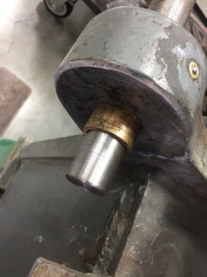
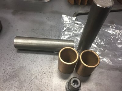
The pins where driven out using a bronze rod after the leaf was removed. They came out easy but then again, I used "Free all" penetrant the day prior. The paint was so thick a socket would not fit but a wire wheel took care of that. I wouldn't be surprised if lead base paint was used somewhere between those coats.
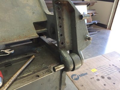
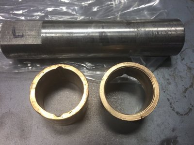
Bronzed bearings as they are called in the manual. The pin fit snuggly into the cast bracket but very loose in the bushings. An oil journal was noted around the center and two legs front/back for the oiler that was painted over.
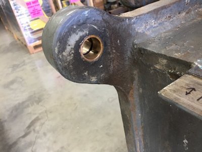
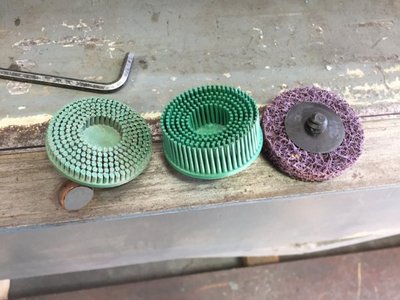
These 3M products remove the layers of paint without cutting into base metal. Kinda expensive, but worth it and the green ones last a long time. The worn out one was used on several projects and is ready to be tossed.
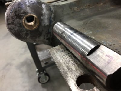
The pivot pins have flat spots for the set screws to bite onto. Better than just round as this can become problematic to remove if a burr is encountered. I have delt with that situation (as many other have) its a PITA. They where thinking on this one.
Waiting on parts quote and I might try to flame straighten the leaf section but probably wait to do it on machine. Back to the lathe/mill cart build.
Incidentally, I used the said cart (prematurely) as a support cart during inspection and teardown. Rolls nice under weight.
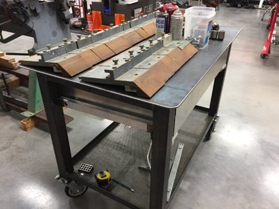
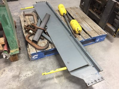
Gona also get some quotes for sand blasting. I don't want to install/press new bushings prior to blasting. Its really a toss up, spending more money on parts/blasting and paint, or reassemble after new bushings to ensure the unit it still salvageable/within tolerances, then disassemble if it proves to be good.
BTW, there is very limited information available on these units, If any tin benders on the site, please chime in. Any advice is always welcomed good/bad or indifferent.
I'm always trying to learn and share my experiences.
Thanks for looking, more to come later.
Turn and Burn!
Paco
Thanks for looking
I made the 130+ mile drive after shift to pick up the unit only to find the forklift operator forked it from the upper clamp to remove the machine from inside storage. This is not advisable and could damage the unit. I had loaded any rigging equipment I thought might be need to load the machine onto a 14K dump trailer I was pulling (little tall).
After removing all the fingers to lighten/balance the pick, I rigged it for picking and that went smooth. Secured the load for my 130+ mile drive home. I used every strap I keep in the rig.


I got home around 2:30 pm and backed in the trailer for the night. I was too tired to unload the unit as I had worked a 24 hour shift that kept us up pretty much all night at explosion/fire that required 4,000 GPM and fifty firefighters. I had it made compared to the guys on the ground handling 2.5" hand lines. It was a defensive fire and we had exposures to protect. I was up 110' operating a Master stream from bucket ladder truck with onboard air (no SCBA required) plugged into my face mask
Anyway, back to the brake,
Unloading the machine from the bottom: I had place some 4"cribbing under the brake running perpendicular to the trailer stringer running parallel to the heavy load at the time of loading. I also didn't want the machine to slide on the metal deck incase of emergency braking. This proved to be very helpful when I unloaded alone. I was able to use 8' fork extensions made some years ago from 6" channel. I was able to approach from the end but needed to drag the unit closer to the end of trailer. This thing is top heavy and off CG as the top clamp section was dislodge when the guy forked it from the bottom portion of the top clamp. The unit wanted to rotate counter clockwise co large C-clamps secured the lower stand to the forks as well as a rigging chain to assist in pulling the machine closer to the trailers a$$ end.
Lifting and gently pulling machine to trailers edge allowing the 8' forks to capture the front stand.

Got it on the ground without drama.

Next up was to reseat the upper clamp back onto the adjusting saddles.
I cribbed the unit leaving the fork extensions in place, then got a shorter 2X4 to use as a spacer under the upper clamp and gently raised the upper clamp to clear the saddle. I then raised the clamp arms using the cam action to line up the saddles and lowered the clamp into position. This went very easy and smooth.
Here you can see the misalignment of the adjuster. Luckily the connecting threaded rod is robust at 2" and supported the knucklehead poor choice of method to move out the machine. Before I reseated, I took the adjuster apart to clean the hard dried grease making it hard to turn. This was put back dry for now and moves freely.

Short section of 2x4 to clear the finger extension mounts under the upper clamp.

Raised it up just enough to rotate the cam lever to align the mouse hole over the L/R adjuster.
Once aligned, I gently lowered the upper clam to its home location. You can see the large clamp
adjustment threaded rod that connects the upper clamp to the lower portion of the table. The robust
design saved the brake from a total failed forklift pick. The sides are 1" thick plates as is the top end plates.

Here you can see the machined bar that supports the finger extensions (behind the 2x4). The
2x4 prevented fork contact during lifting of top clamp. Also notice the table and bending leaf hardened
Bar. The machine will require a bending angle bar to bend to capacity. A common piece of 1/4"x2" angle should
do the trick so long as its straight.

A total of 15 fingers and one custom made. I still need to inspect for damage, but right off the bat
they will beed to have the bottoms reconditioned. I also noticed one with damage from bending rod

Spent a full day trying to adjust but found myself removing hardware to clean multiple coats of paint.
I also removed the table hardened bar to flip, the back side a virgin. The problem is two or three holes where drilled at the factory slightly misaligned. I should be able to slot them slightly using a mag drill. I was unsuccessful in aligning the leaf to the table by .0858". I decided to further tear down the folding leaf and inspect the pivot point for excessive wear that could be preventing the realignment. Working alone takes creative thinking at times when picking heavy items that want to rotate such as the leaf. I rotated the leaf 180º and secured a rigging chain and took up slack, then removed the two counter weight prior to removing the ten bolts.

The pins where driven out using a bronze rod after the leaf was removed. They came out easy but then again, I used "Free all" penetrant the day prior. The paint was so thick a socket would not fit but a wire wheel took care of that. I wouldn't be surprised if lead base paint was used somewhere between those coats.

Bronzed bearings as they are called in the manual. The pin fit snuggly into the cast bracket but very loose in the bushings. An oil journal was noted around the center and two legs front/back for the oiler that was painted over.

These 3M products remove the layers of paint without cutting into base metal. Kinda expensive, but worth it and the green ones last a long time. The worn out one was used on several projects and is ready to be tossed.

The pivot pins have flat spots for the set screws to bite onto. Better than just round as this can become problematic to remove if a burr is encountered. I have delt with that situation (as many other have) its a PITA. They where thinking on this one.

Waiting on parts quote and I might try to flame straighten the leaf section but probably wait to do it on machine. Back to the lathe/mill cart build.
Incidentally, I used the said cart (prematurely) as a support cart during inspection and teardown. Rolls nice under weight.


Gona also get some quotes for sand blasting. I don't want to install/press new bushings prior to blasting. Its really a toss up, spending more money on parts/blasting and paint, or reassemble after new bushings to ensure the unit it still salvageable/within tolerances, then disassemble if it proves to be good.
BTW, there is very limited information available on these units, If any tin benders on the site, please chime in. Any advice is always welcomed good/bad or indifferent.
I'm always trying to learn and share my experiences.
Thanks for looking, more to come later.
Turn and Burn!
Paco
Thanks for looking


