

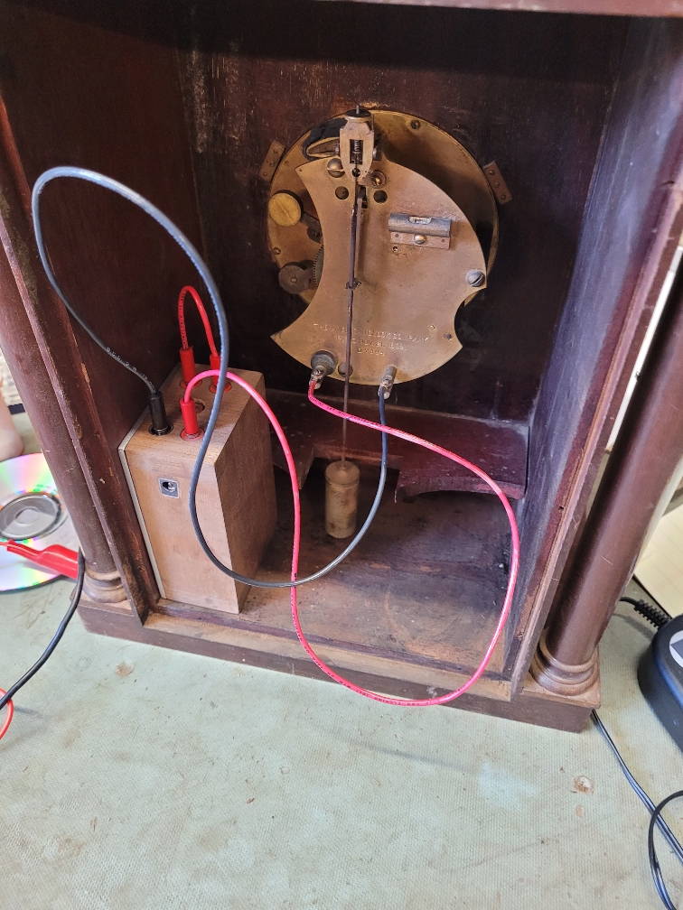
We have an electric clock from 1901 to 1905.
It is a self winding type, runs on a pair of 1.5 volt ignition batteries, is hard to find, and is expensive.
Given that we are cheap, we had to be made with what we had handy.
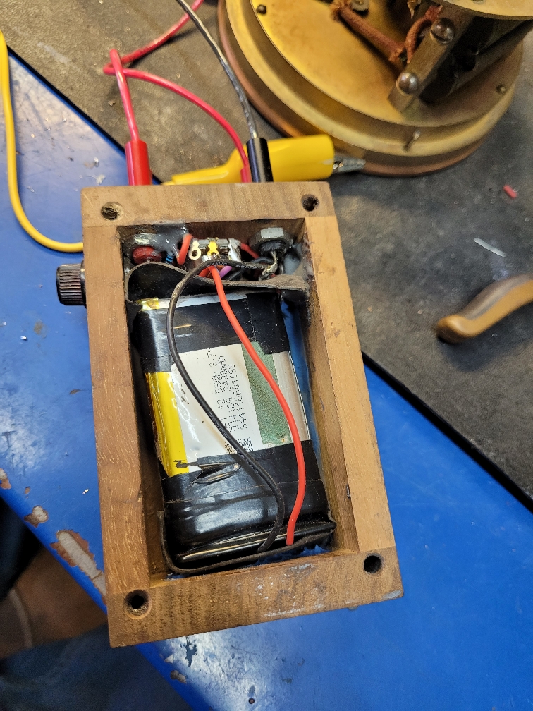
We had a brand new battery for a communications radio that the charging circuit failed, got a warranty replacement, and did not need to send it in, so we opened it up.
Inside were 2 flat-pac Lithium batteries, 3.7 volts @ 3400 mA, modified the combiner board to make them parallel instead of series, so 3.7 volts @ almost 7 amp hr
The clock has a switch that grounds the internal solenoid that winds the clock. This switch is on a shaft, so we want to reduce the chance of sparks.
Plus, the original was 3 volts or a little less, 3.7 with high current needs control.
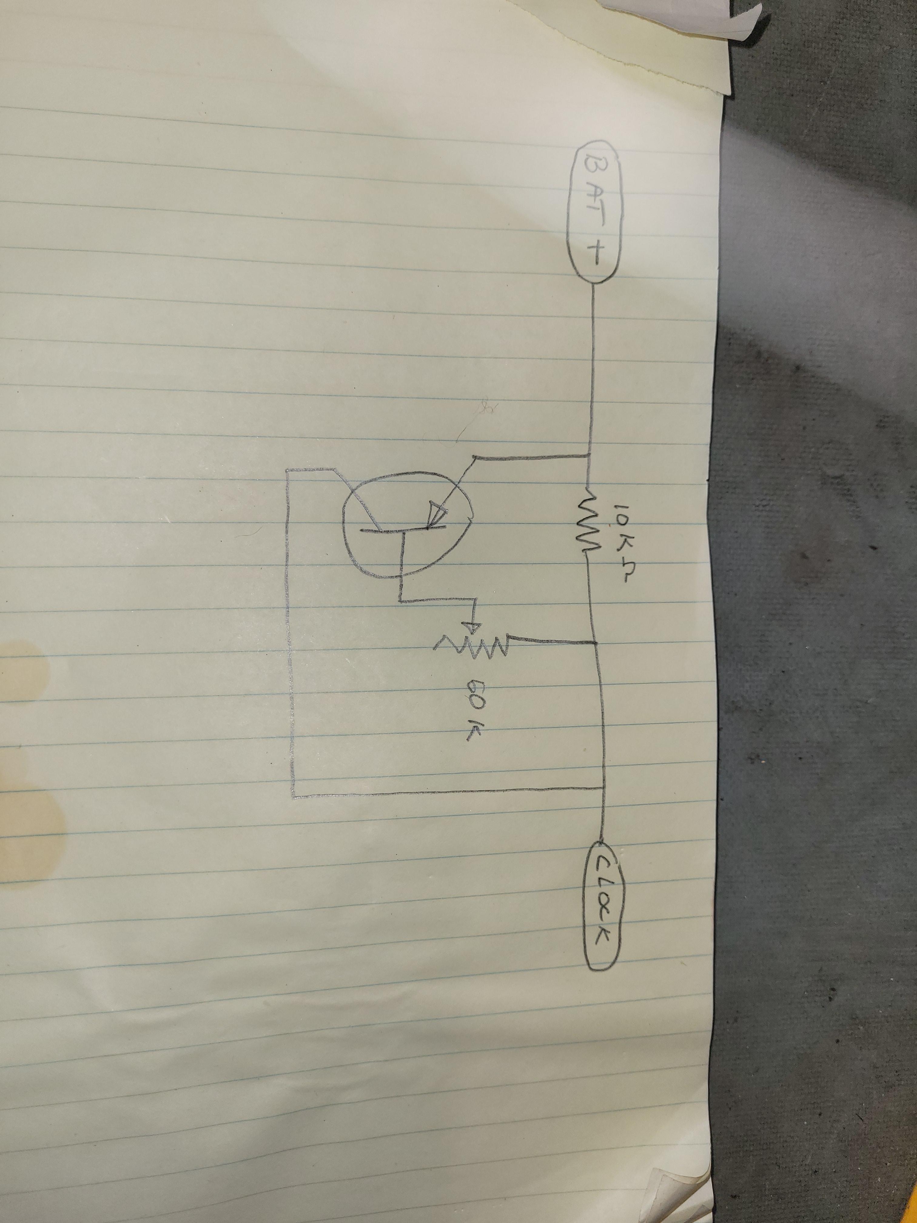
Using a modified trick we learned years ago, we made a current control system that removes the spark on the make contact and controls the current.
From the battery, we added a 10 K resistor.
From the clock side, we connected a 50 K pot.
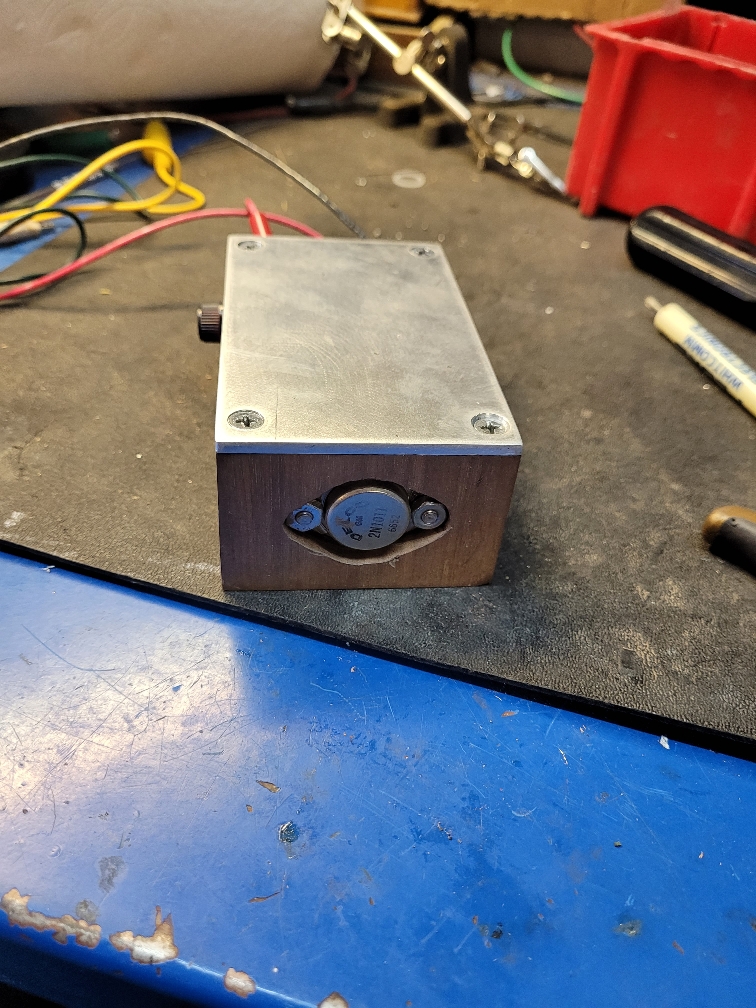
We had some PNP TO3 cased Germanium transistors, the emitter to battery, collector to clock, and pot wiper to base.
The switch closes connecting the 10 k resistor buffered battery to coil.
Voltage drop across the 10 k turns on the transistor.
The pot varies the drive, so current is controlled.
The transistor bypasses the 10 k resistor supplying controlled current to clock.
The current is normal 0.5 amps, set to 0.45 amps to reduce stresses.
Estimate it should last 6 to 7 years on a charge.
The pot was locking type, bonus.
The loop is to measure current.
Added a charge port, found a wall wart style Lithium charger to charge the batteries.
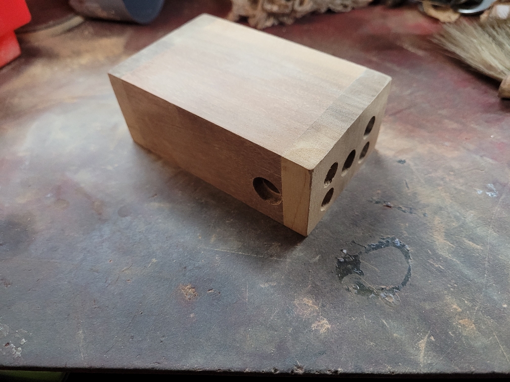
The small wood box required some layout to make it all fit, took a few tries on paper, the fuse holder is just a bit too long, cut the recess just a bit too deep, a washer fixed that.
The parts are designed for panel mount, wood was 0.3 thick, nothing would work, so counter-bored everything to fit flush.
All but fuse holder.
Sent from my SM-G781V using Tapatalk
It is a self winding type, runs on a pair of 1.5 volt ignition batteries, is hard to find, and is expensive.
Given that we are cheap, we had to be made with what we had handy.
We had a brand new battery for a communications radio that the charging circuit failed, got a warranty replacement, and did not need to send it in, so we opened it up.
Inside were 2 flat-pac Lithium batteries, 3.7 volts @ 3400 mA, modified the combiner board to make them parallel instead of series, so 3.7 volts @ almost 7 amp hr
The clock has a switch that grounds the internal solenoid that winds the clock. This switch is on a shaft, so we want to reduce the chance of sparks.
Plus, the original was 3 volts or a little less, 3.7 with high current needs control.
Using a modified trick we learned years ago, we made a current control system that removes the spark on the make contact and controls the current.
From the battery, we added a 10 K resistor.
From the clock side, we connected a 50 K pot.
We had some PNP TO3 cased Germanium transistors, the emitter to battery, collector to clock, and pot wiper to base.
The switch closes connecting the 10 k resistor buffered battery to coil.
Voltage drop across the 10 k turns on the transistor.
The pot varies the drive, so current is controlled.
The transistor bypasses the 10 k resistor supplying controlled current to clock.
The current is normal 0.5 amps, set to 0.45 amps to reduce stresses.
Estimate it should last 6 to 7 years on a charge.
The pot was locking type, bonus.
The loop is to measure current.
Added a charge port, found a wall wart style Lithium charger to charge the batteries.
The small wood box required some layout to make it all fit, took a few tries on paper, the fuse holder is just a bit too long, cut the recess just a bit too deep, a washer fixed that.
The parts are designed for panel mount, wood was 0.3 thick, nothing would work, so counter-bored everything to fit flush.
All but fuse holder.
Sent from my SM-G781V using Tapatalk
Last edited:
")
 . Now you got overkill.