I thought members would be interested in my implementation of Clough42's ELS.
Hardware:
The spindle has a 40 M1.5 tooth pinion so I made a 40 tooth 1.5 gear out of polypropylene from a domestic breadboard and drive it via a metal idler on the banjo of the lathe with a suitable bushing and spacer pined to the fabricated gear to align the gear set. I bent up a s.steel bracket from !.5 mm material and attached the Encoder to the banjo using one of the banjo T nuts.
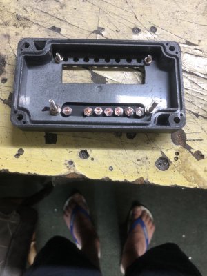
The hybrid stepper is nested in the space under the spindle with a s.steel bracket bent to the correct offset to align the pulleys and secured with M4 screws The belt is T5/16 2:! ratio. The bracket for the stepper has slotted attachments so it can be moved laterally to adjust belt tension. The installation feels vey secure and is quiet running. I enclose a couple of photo's to give you a visual picture.