CNC porting of cyl. head on 3 axis + 3d scanning of ports

spaceman_spiff

Active User
Registered
Joined
Oct 20, 2014
Messages
159
My goal is to CNC port the cylinder head for the 2.2/2.5 Chrysler 4 cylinder k-car from the 80's and 90's.

I have broken this down into a few steps:

Step 1. Make silicone mold of ports and combustion chamber (silicone off ebay for about $40)
Step 2. Scan molds using laser scanner (DAVID scanner + barcode laser line generator)
Step 3. Create 3D model of mold scans using Geomagic and Solidworks
Step 4. Use 3D model as a guide to create a custom combustion chamber and intake/exhaust runners
Step 5. Use Camworks to create toolpaths and machine cylinder head runners and CC on 3 axis using a few fixed setups.

So far I've gotten to step 5, but only for a small part of the combustion chamber.

I believe that using all the CAD and CAM software tools, you could reach all required internal geometry on the head using just a 3 axis mill with a couple fixed setups.

The CAD and CAM software do their job and help you figure out how to get to all the surfaces on a 3 axis with minimal setups.

If you take your average cylinder head, and say a 3/8" rod, you can see that most of the surfaces are visible from one perspective. Now add a few more vantage points and a tool that can undercut like a spherical ball mill or just a ball mill with a reduced shank, and you can get to 100% of them, at least on this head.

So I think this can be done on a 3 axis with minimal additional setups.

Keep in mind that the scans of the head only function as guides. Whatever design you want for the CC and runners gets drawn up in Solidworks from scratch, and you can use the existing stock surfaces to help you figure out how far you are straying from existing geometry. The only critical scanned locations are things like the valve seat centers, valve guide, planes at the head gasket and intake manifold gasket surfaces, etc..in other words, things that are machined can act as datums. You cant use the cast surfaces as datums because of core shift. Besides, we arent here to keep the existing surfaces, we're here to destroy them MUHAHAHAH

Heres what I've done so far:

20140804_183331_zpspoayk8hm.jpg

20140805_084907_zpsgiwaosdr.jpg

20140805_085951_zpsjtwkrio6.jpg

20140805_163907_zpsyk3ktfk5.jpg

20140805_164935_zps60qnojj7.jpg

20140805_223940_zpspuil6zyi.jpg

20140805_223931_zpslmescbuu.jpg

20140805_152520_zpsu5wvnjd2.jpg

20140805_153335_zpsxpey4ghp.jpg

scanexample2_zps26ebb291.jpg

scanexample_zps8932e018.jpg

twoscans_zps6b037155.jpg

swport_zps20633882.jpg

deshroud_zpsbe147c02.jpg
toolpath_zpsd571129e.jpg
20140815_181436_zps8ka0jsol.jpg

20140815_184457_zpseh01k3qi.jpg

20140815_192711_zpsuzrabcux.jpg

20140815_193239_zpslqickd63.jpg

20140804_183331_zpspoayk8hm.jpg

20140805_084907_zpsgiwaosdr.jpg

20140805_085951_zpsjtwkrio6.jpg

20140805_163907_zpsyk3ktfk5.jpg

20140805_164935_zps60qnojj7.jpg

20140805_223940_zpspuil6zyi.jpg

20140805_223931_zpslmescbuu.jpg

20140805_152520_zpsu5wvnjd2.jpg

20140805_153335_zpsxpey4ghp.jpg

scanexample2_zps26ebb291.jpg

scanexample_zps8932e018.jpg

twoscans_zps6b037155.jpg

swport_zps20633882.jpg

deshroud_zpsbe147c02.jpg

toolpath_zpsd571129e.jpg

20140815_181436_zps8ka0jsol.jpg

20140815_184457_zpseh01k3qi.jpg

20140815_192711_zpsuzrabcux.jpg

20140815_193239_zpslqickd63.jpg
 
Now add a few more vantage points and a tool that can undercut like a spherical ball mill or just a ball mill with a reduced shank, and you can get to 100% of them, at least on this head.

Google ''Lollipop cutter''

This is very cool. Please keep us posted on your progress.

I am going to be looking at DAVID Laser Scanner, I need that because I don't have it.:whistle:
 
Google ''Lollipop cutter''

This is very cool. Please keep us posted on your progress.

I am going to be looking at DAVID Laser Scanner, I need that because I don't have it.:whistle:

The lollipop/spherical cutters only come up on ebay once in awhile and they are $$$...theres one now for $65 that I've had on my watch list for months, http://www.ebay.com/itm/190717798779?_trksid=p2055119.m1438.l2648&ssPageName=STRK:MEBIDX:IT

I'm not actually sure if I need it or not. Hopefully not. Since you get to design the new surfaces and almost certainly everything gets bigger in one direction at least until the bowl, I'm hoping that I can just use standard tools or possible just end mills with reduced shanks.

DAVID scanner is very important, or some kind of 3D scanner software which does a great job of stitching the scans together. I tried using makerscanner, but you cant get the laser at multiple angles and you cant stitch the scans in it. With DAVID scanner its pretty easy and its stitcher works great. Plus you can angle the laser anywhere and get all the nooks in crannies. I think I needed about 5 different scans, flipping/rotating the casting, to generate that intake runner.
 
that's really cool, especially the scanning part. I didn't catch the "why" though - are you trying to increase squish volume (if that's the right phrase) to turbocharge the engine? In other words to lower the compression ratio? I'm not well up on the design of 2 valve heads like that, so I don't know if there have been improvements to how the flame front and combustion mix swirl is managed since then. I was always under the impression that most tuners worked on opening up and profiling the ports/ runners to improve hp, but then again, what I know about tuning engines could be written on the back of a stamp :)
 
This is interesting, and something that I had thought about doing, but never got around to it. A rotary 4th axis would go a long way to reducing the number of setups needed. One thing that you will likely need to do is come up with several port designs and test them on a flowbench, if you want to get optimum performance. If you can get some heads that are basically scrap (cracked, has a combustion chamber pounded out by a dropped valve, etc.) you can run each port with a different program, then test them. I don't see why you couldn't use the rotary cutters normally used for hand porting to reach those hard to get areas. You would have to do light cuts, due to the springiness of the shank. You could also fabricate your own cutter, similar to a fly cutter, to reach the most onerous areas. Good luck.
 
that's really cool, especially the scanning part. I didn't catch the "why" though - are you trying to increase squish volume (if that's the right phrase) to turbocharge the engine? In other words to lower the compression ratio? I'm not well up on the design of 2 valve heads like that, so I don't know if there have been improvements to how the flame front and combustion mix swirl is managed since then. I was always under the impression that most tuners worked on opening up and profiling the ports/ runners to improve hp, but then again, what I know about tuning engines could be written on the back of a stamp :)

The engine is already turbocharged. Im not an experienced racer or engine builder by any means. I have a general idea what needs to get done here but mostly I am doing what the crowd on the TD/TM forums want. From what I can tell, its pretty standard stuff:

-deshroud the valves
-make the runners much larger and smooth entry into the bowls
-transition the surfaces going up to the valve guide so a splitter is made
-make the bowl a spherical shape instead of the mass produced conical shape

And the usual smooth and other things.

This head was probably designed in the late 70's..
 
This is interesting, and something that I had thought about doing, but never got around to it. A rotary 4th axis would go a long way to reducing the number of setups needed. One thing that you will likely need to do is come up with several port designs and test them on a flowbench, if you want to get optimum performance. If you can get some heads that are basically scrap (cracked, has a combustion chamber pounded out by a dropped valve, etc.) you can run each port with a different program, then test them. I don't see why you couldn't use the rotary cutters normally used for hand porting to reach those hard to get areas. You would have to do light cuts, due to the springiness of the shank. You could also fabricate your own cutter, similar to a fly cutter, to reach the most onerous areas. Good luck.

Yes I will probably cheat and use the 4th axis I'm working on instead of manual angled setups. But I really do think it could be done on a few fixed setups. Probably get the entire bowl from one side. Then the runner done in maybe 3 setups..straight on, and maybe two more at 15 degree angles. Even a manual rotary table would make it cake.
 
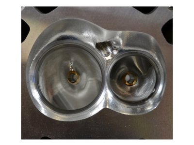
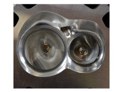
Heres a modern chevy LS3 head with a CNC ported CC..basically exactly what I am shooting for. Deshrouded valves and everything smoothed out. The runner and bowl are alot more complicated.

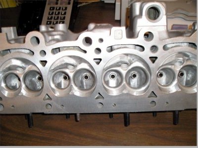
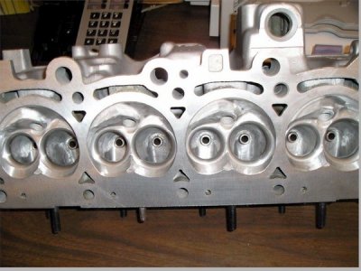
And below that you can see the same head I'm working on, but hand ported by someone with alot of hard work.


TSP199-PRCLS36B250_D.jpg

18099d1139956904-swirl-head-combustion-chamber-rob6.jpg

TSP199-PRCLS36B250_D.jpg

18099d1139956904-swirl-head-combustion-chamber-rob6.jpg
 
So this is mostly a project to demonstrate CNC capabilities? Because with forced induction seems like you will only realize marginal HP gain. And I don't think I read any warnings about "hitting water?"
 
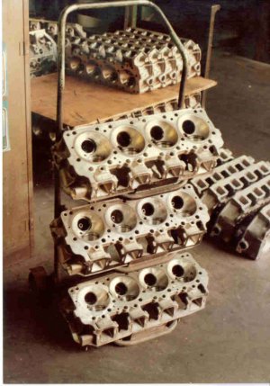
Interesting to me where modern innovation and technology has come. I ported by "hand" thousands of heads for Top Fuel and Alcohol Chrysler Hemi's in the 80's for all of the top pros on the racing circuits when I worked for Keith Black Racing, as well as a zillion 2 stroke dirt bikes. Never thought it would come to this.

engine5.jpg

engine5.jpg
 
Back
Top