- Joined
- Feb 7, 2018
- Messages
- 164
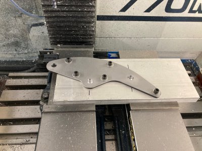
I work for an aviation OEM as my day job and one of the parts we manufacture is a time consuming set of brake lines. While we do have some pretty tech CNC tubing benders these lines (mirror images) have both bends and a coil in them. This combination has led to some work arounds in the process since our benders can't do both. Over the years this has really amounted to a lot of time lost, but since we don't have any other work for an actual machine that can both coil and bend the justification just wasn't there for a purchase. I proposed an alternate solution which was to finish bend the tube and leave the coil section until the end. A dedicated set of hand coil winders would perform that operation at much lower cost. I came up with a design in CAD and with them onboard with the concept they decided to ok this project. With the exception of some laser cutting/bending (SendCutSend), TIG welding, and powder coating I machined everything else at my home shop.
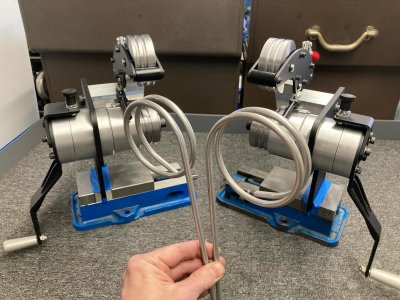
For a project that took almost 5 months I surprisingly didn't take many pictures along the way, but I do have some nice finished shots. The actual tubes are more complex than what is shown here. This was just some sample tubing to roughly get the machines setup.
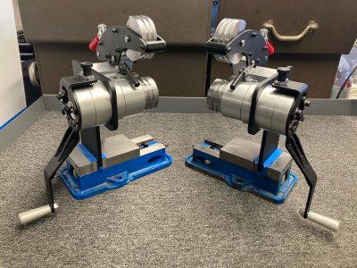
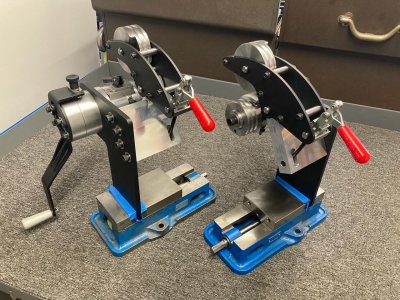
These will either be held in a bench vise when in use or utilize a couple slots on the base to bolt directly to the workbench. These spare D40s came in handy during the build as some temporary bases.
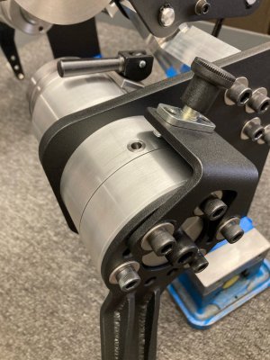
Spring plunger holds the handle in position so the load position is the same every time.
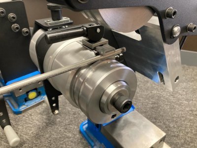
Tube is clamped into place quickly with a cam lever. Actual tube has a bend on it that is located against an adjustable stop.
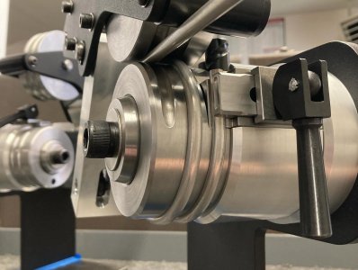
The winding motion is smooth and not much too much work, but not insignificant either.
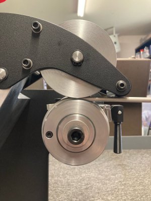
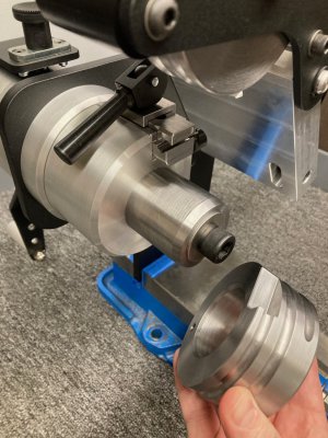
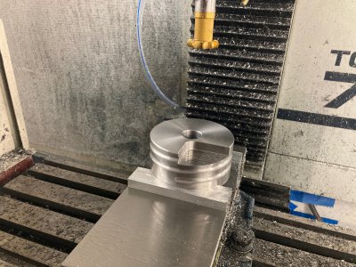
I originally wondered if the die that the tube is coiled around would need to be taken off to remove the tube. The die was made to be removable for this reason. As it turns out there is so much spring back that the tube can easily slide off. A socket head cap screw was added to just keep the die from sliding off and ending up on the floor. The tubing clamp also acts as the drive lug for the die itself.
-Nick
For a project that took almost 5 months I surprisingly didn't take many pictures along the way, but I do have some nice finished shots. The actual tubes are more complex than what is shown here. This was just some sample tubing to roughly get the machines setup.


These will either be held in a bench vise when in use or utilize a couple slots on the base to bolt directly to the workbench. These spare D40s came in handy during the build as some temporary bases.

Spring plunger holds the handle in position so the load position is the same every time.

Tube is clamped into place quickly with a cam lever. Actual tube has a bend on it that is located against an adjustable stop.

The winding motion is smooth and not much too much work, but not insignificant either.


I originally wondered if the die that the tube is coiled around would need to be taken off to remove the tube. The die was made to be removable for this reason. As it turns out there is so much spring back that the tube can easily slide off. A socket head cap screw was added to just keep the die from sliding off and ending up on the floor. The tubing clamp also acts as the drive lug for the die itself.


-Nick

