Considering switching to VFD from Rotary

Ah, I understand now. I'm not liking the idea of motor control via the VFD. I think my best plan will be move RPC to a quieter space and leave things as they are.

Just for giggles, tell me what happens if I try to use the switches on my machine downstream from the VFD

A standard feature of VFD's is "soft start". The VFD spins the motor up over a period of time instead of near instantly. This GREATLY reduces the amount of current needed to start the motor. The inrush current from hard starting a motor near instantly is many times that of the motors typical run current.

By engaging a motor with a switch between the VFD and the motor you are doing a hard start instead of a soft start. Modern (inexpensive) VFD's are not designed to handle the full inrush current of hard starting the motor. Most likely the VFD will just throw an error and turn off. If the VFD's over current detection doesn't kick in you will likely fry the power transistors in the VFD. Repeatedly tripping the VFD's over current circuit is probably not very healthy for the VFD and will most likely take its toll on the VFD over time.

If you wire your shop for 3 phase and plan for your RPC you can always add VFD's to your machines later if you want to make use of the variable speed control or electronic braking capabilities of a VFD.
 
Last edited:
I've had an RPC and I can't see why anyone would want one over a VFD. VFDs give you so much control so easily and can be right next to the machine so everything is at arms reach.

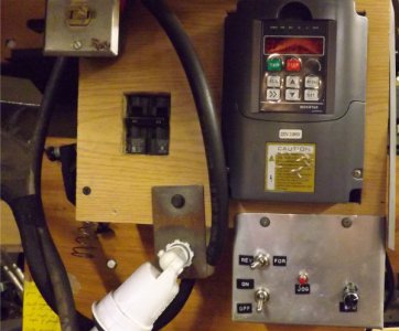
This is how mine is set up. The breaker to the left controls power. I never touch the VFD panel controls,
only the added on stuff below. Machine lights are controlled by switch in upper left corner.
DSCF4042.JPG

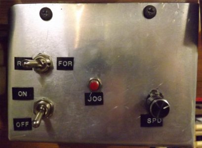
This is my added control panel. Simple on/off, forward/reverse and frequency pot.
I have never used the jog feature. So many other things are available with VFD also.
DSCF4041.JPG


With VFD you get motor protection (over current, temperature, stall and others), ramp up/down speed control, emergency stop and instant reversing.

I also run my surface grinder off this same VFD (similar motor chacteristics) by just plugging in the proper 3-phase plug (one machine at a time).
 
I agree completely. I just fitted a Fuji Frenic mini VFD to my 3-phase PM-835S mill. It has remote control via a panel I built, soft start, very fast braking thanks to the cheap (and huge) finned resistor I got from Ebay, and as an added bonus, when I put it in back gear it automatically reverses the controls so forward still means forward. Programming is not very simple but you soon get the hang of it. Many complain of the possibility of induced motor noise but judicious setting of the switching frequency and the use of ferrite beads on input and output leads and a 240V input filter appear to smooth everything out and, so far, I have detected no issues with it.
 
What did you use to tell it it's in back gear?
 
A reed switch and a magnet. The reed switch is simply wired to one of the multi-purpose inputs (pull-down) to reverse direction and the magnet is on the back gear control lever. Took a bit of time to find the best place to put the switch as my mill has a complex, home-brew power drawbar, but neodymium magnets are so strong they can work over a goodly distance.
 
One more thing to consider with a VFD is that some of the VFDs do not have well filtered outputs and can only be used on inverter duty motors. If you have an old machine it likely does not have an inverter duty motor. Not all new motors are inverter duty either. If the output of the VFD is well filtered and is giving a true sinusoidl output then it will be fine on the older motors.
 
One more thing to consider with a VFD is that some of the VFDs do not have well filtered outputs and can only be used on inverter duty motors. If you have an old machine it likely does not have an inverter duty motor. Not all new motors are inverter duty either. If the output of the VFD is well filtered and is giving a true sinusoidl output then it will be fine on the older motors.
No VFD produces a "true" sinusoidal waveform. It is an approximation created by high speed switching. While it is true that some motors may be less tolerant of this than others, altering the switching frequency can have a dramatic effect, as can output filtering to reduce higher frequency harmonics.
 
With enough filtering you can get the PWM output darn close to a sinusoidal output. Not perfect but close enough.

A very layman explanation of a VFD.
A VFD works by taking the 240 1ph in and converting it to 340V DC, a bunch of transistors then take the 340VDC and by switching on and off real fast sends an output that to an inductive load like a motor resembles a 3ph wave form.

It is that constant barrage of 340VDC peaks in the output that will break down the insulation of the motor winding in a non inverter duty motor. An inverter duty motor simply has an insulation package that is designed for the 340 volts.
At a high enough frequency the inductive elements of a motor offer almost infinite impedance to a high frequency electrical impulse.
It's like music. A CD samples the musical waveform at 44KHz and that is high enough that a human cannot hear that it is not a sinusoidal frequency (or at least a component of it). This does not prevent some people preferring the distortion induced by RIAA correction of the pre-distorted signal applied to vinyl records.
Please back up your proposition that some motors cannot by driven by a VFD with some empirical evidence. The use of ferrite beads on the 3-phase output leads is done to prevent RF interference with external electrical equipment like tuners and amplifiers, not to protect the motor.
I cannot see a mechanism for any harm to be done to the motor unless an unnecessarily low sampling frequency is chosen.
What exactly is the definition of a "non-inverter duty" motor?
 
The beauty of a quality RPC is, all your 3 phase machines plug into the disconnect or outlet and operate as designed.
Simple, clean install. My 10hp American Rotary is very quiet. When I turn on my mill or lathe, I don’t hear the RPC.
 
Back
Top