Convert a manual grinder to auto feed?

I am planning to make a quick release to be able to mechanically disconnect the shaft from the motor in case I want or need to go full manual, like for dressing the wheel. This will be the hardest part (at least for me) as I need to make a sliding male and matching female splineish something using the machines I have to work with and NOT buy any expensive tooling. The spline will need to be big enough to put into a tube that has a 20mm ID to fit the machine shaft. There will also need to be a detent to hold it either open or closed. I am still open to ideas on how to accomplish all this. I have never even thought of trying to make matching splines.

Here is how I did a zero backlash quick disconnect. That's a NEMA 23 motor. This system was designed to be able to quickly change out the piece that it drives, but would work just as well driving another shaft. Easily built on a lathe and mill.

Five 3/16 dowel pins, slide into mating holes in a piece of UHMW. Make the holes in the UHMW a tight fit, it will expand to accommodate. In this case the motor moves in & out on a dovetail for alignment. This coupling will take some misalignment.

297985


297986


297987


297988


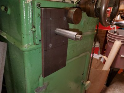
You want to mount the limit switches such that the table be able to slide by the limit. Normally the limits are mounted at different heights on the apron of the machine, and are actuated by cams that are adjustable down the length of the table using the T-slot in the front of the table.

You can see the adjustable cams in this picture of my machine, in this case the cams actuate the directional lever (center pic) but a limit switch in the place of the lever would be my choice.
297989
 
I may be able to come up with something that slides on and off of pins. Or It might be just as easy to simply loosen the set screw on the drive pulley to let the shaft spin in the pulley. Tightening it would be difficult because I would have to find the flat on the shaft for the set screw to tighten to.

I see now. I was thinking all backasswards on the limit switches. I was thinking I had to mount the switches to the cams. My poor old little brain never even thought of mounting the switches to the machine and let the cams actuate the switches. This would also mean that I do not have to have wires flying back and forth with the table movement.
 
Pics of the very beginning of letting the chips fly.
I have the 4 mounting holes drilled and tapped into the front of the grinder around the tables drive shaft. I already have the wheel and spacer removed from the shaft. As soon as I make a proper pilot I will use a counterbore to spot face the 4 holes so that the spacers will sit flat and not try to follow the rough cast surface.

20190709_212739.jpg

The second pic is the beginnings of the mounting plate that will be on 4 standoffs. the holes that are currently in the plate were for match drilling the machine. I will go back in and open all 5 of those holes into slots for belt adjustment. It is a major PITA to remove that plate from the machine.

20190709_212800.jpg
 

Attachments

  • 20190709_212800.jpg
    20190709_212800.jpg
    42.9 KB · Views: 258
  • 20190709_212739.jpg
    20190709_212739.jpg
    47.5 KB · Views: 250
Last edited:
I now have the mounting plate nearly done.
The original mounting holes were drilled with a #7 drill bit so that they would work as drill bushings for the drill and tap of the machine, they have now been opened up to 1/4 by 1/2 slots to allow for belt tightening.
I just have to open up the hole that the machine shaft goes thru. I initially made it to match the shaft so that I could use the plate as a drill guide for putting the mounting holes in the machine. Now I have to open it up for the machine boss and the spacers that will line everything up. Size and finish is not critical and no one will see it once installed, So I will just use around a 2 inch hole saw with 2 holes spaced 1/2 inch apart and clean up the points with an end mill to make it a 2 inch wide x 2-1/2 long slot to match the mounting slots, and call it close enough. Then I can start with mounting the motor to the plate and the plate to the machine. Once I get that done I can take the final measurements for the length of spacers that will be needed to finish the stack up on the machines table drive shaft. For the motor end of the plate, I drilled and tapped mounting holes and nose relief for a NEMA 23 on one side of the plate and a NEMA 34 on the other side of the plate. Just in case the 23 is not strong enough to do the job. It was a lot easier to add the relief and hole for the 34 as long as it was all set up and indicated in on the rotary table. T

It has been slow going, temps are supposed to be pushing 100°F with super high humidity (dew point hitting 80°F) for good measure. I am old and can not tolerate that kind of heat anymore. It is supposed to be cooler next week.

Pics of the plate will be coming as soon as I can get that last hole done and some paint squirted on it to match the paint I used on the rest of the machine. OR maybe I'll just clean it up and use some gun bluing on it. I did machine all of the outside edges just to true it up. I could slap it on the surface grinder to make the front pretty and then just leave it looking like a ground surface. Hmmmmmmm........... decisions, I have never had any artistic flair as to what would look good. This plate is steel, if it were aluminum I would leave it plain. I just happened to have a chunk of 3/8 thick steel plate laying around when I started this, and no aluminum plate laying around.
 
Well I was delayed again, had to deal with dad going into hospice and finally passing and then the funeral stuff. That is all behind me now and it is time to get back to life.
I did make the mistake of working on this some while all this was going on, my brain must have not been functioning properly because 2 of the holes in the stepper mounting pattern are drilled and tapped exactly .100 off from where they should be. SO now my choices are to slot those 2 holes and just use a screw and nut to attach the stepper, or weld the holes closed, clean up the weld, anneal the weld, and then drill and tap in the correct spot. I am leaning toward just slotting the 2 offending holes since once the nuts are on, no one will ever see the slots and this will be a LOT faster.
 
We have more progress.
I have the stepper motor and the belt drive all mounted up on the grinder. Plugged in the electronics I built earlier and the table even moves back and forth now.
WOOOOOO HOOOOOO

I still have to mount the switches for the table reversing. Right now I am just holding one switch in each hand and clicking to reverse direction. But I just had to see the table move under its own power.

Now for the issues......
#1 The motor does not have enough torque to handle the acceleration from stop and table reversing. They will keep it going if I help it get started.
The motor that I have is a NEMA 23, x 57mm long, 6 wire motors, I have them wired as 4 wire. I am running the motor at 48V (tried 24V first but it was way to weak). If I turn the speed all the way down then there is just enough torque to do the reversing, but that is to slow of a speed for normal grinding. There are several ways to wire up the 6 wire motor, Will I get more torque by using the center tap and one end or by using both ends of a coil and leaving the CT unconnected. Will a true 4 wire motor give more torque than the same size 6 wire run on 4.

#2 The fastest speed that I can set on my controller is barely fast enough. I have a 2 x 1 reduction in the drive belt. If I reduce the steps per revolution I will get more speed (or is it the other way around?), But will this also reduce my torque. What settings on the driver are best for maximum torque?

#3 I do have room for a longer NEMA 23 motor this will give me more torque that I need and should allow me to speed things up. BUT will it be enough? I also drilled the hole pattern for a NEMA 34 motor on the other side of the mounting plate. The shortest 34 is still more torque than the biggest 23? And the short 34 will fit better than the long 23. I have to do more measuring but I think the longest 23 will kit the base casting. I am not sure if I can flip the big pulley to put the hub on the inside to gain enough room. Lots more measuring to do.

Now that I have typed this all out I think I am leaning to the short NEMA 34?????

Stepper-Mounted.jpg
 
I will be rewiring to use full coil and then playing with the driver settings to see if i can get there with this motor.
If not, I found a 637 oz NEMA 34, 4 wire, on Amazon for $10, last one. I may just snag it just in case.

This is the driver that I have.
The driver is 50VDC max I am at 48VDC. I did this by connecting two 24V supplies in series.
I do have another 24 V supply so I could go up to 72VDC but then I need a new driver.

This is the stepper motor that I have
Nidec servo corporation 4522
kh56km2u121
I have not been able to find this exact motor to get the specs for. There are motors listed that are very close in P/N, I believe that this is a proprietary motor made for a specific printer manufacturer and that is why I can not find specific data.

And this is the controller that I have.
I have pulled the direction switch off the board and wired in a latching relay and the relay is controlled by the 2 limit switches for reversing at the ends of travel.
 
Last edited:
Have you got the current on the motors turned up to where it should be? That will dramatically affect the torque. If you don't have the current specs for the motor, then keep bumping up the current until the motor is too hot to hang on to after running for about 10 minutes. Those motors will easily take 60°C (140°F)
 
The only info I could find was from an ebay ad that it was a 2 Amp motor so that is what I have it set for. I will start cranking that number up. Right now the motor is still running at room temperature. NO heat at all.

Does the load mater in generating motor heat like a "normal" motor, or do steppers make the same heat regardless of load?
 
Back
Top