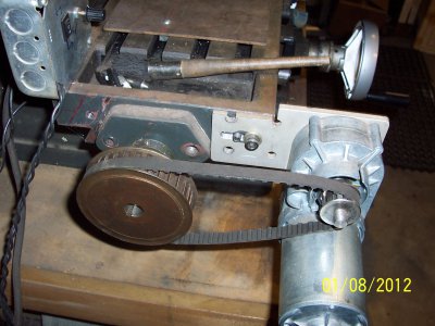
Converting Elec Drill Motor To Table Drive.

T Bredehoft

Active User
H-M Supporter Gold Member
Joined
Dec 27, 2014
Messages
4,060
I have an incentive to re-motorize a carriage that rides on ways, is now cable driven. There is room under it for a drive screw, I have a 1/3 horse reversible adjustable drill motor but don't have the engineering smarts to mount the motor. I am thinking I'll have to mfg a housing for the motor, but don't know where to start. I've tried dimensioning the gear sleeves on the drive end, but not with a lot of success.
All suggestions considered, thanks extended.
 
A few ideas:

-you might replace the cable drive with a chain and sprocket drive; it might be easier than trying to find/make new mount points for a lead-screw
-how about a motor that already has a housing...perhaps from a car seat position system, fairly cheap at a wreckers, they are reversible, but are 12VDC

-brino
 
Nice post brino, I'll add that they have a bunch of torque as well if they are able to move a 300lb human plus the weight of the chair
 
There are a lot of gear motors out there on eBay. In designing a power drive, you need to consider several factors. First, you would want to to have variable speed so that fairly well rules out ac induction motors. Brush type motors are the easiest to control but steppers could also be used.

Second, what is your desired top speed for traversing the table? If you have a .1" pitch lead screw, and want to move at 100 in/min. maximum, you will need a 1000 rpm motor.

Third, what are your torque requirements? This can be rather difficult to guesstimate. Here is one way: take a pull type scale (fish scale, etc.) and attach it to the crank. Pull on the scale to rotate the lead screw while trying to keep the direction of pull at a right angle to the line between the handle and the lead screw shaft. If your pulley has a flat circumference, you could wrap a tape or cord around it ad attach that to the scale. That insures that you are always pulling at a right angle. The scale reading in pounds times the distance from the crank to the lead screw shaft (or, you're using the circumference of the crank handle, the radius of the crank handle) will give you the torque in inch-lbs. I measured my old mill/drill and came up with about 20 in.- lbs. and the stepper motors on my Tormach are rated at about 30 in.- lbs.

Finally, you have to consider the interface. How large can the motor be, how will you mount the motor, can you conveniently disconnect the motor for manual operation, how do you connect the drive shaft to the lead screw, etc. while a drill looks attractive from power source perspective, mounting one would be a nightmare.

Bob
 
Bob, my application is not a mill, but a carriage, mounted on a way. The carriage holds a block (for instance 1 by 1 1/4 by 10") of balsa. It is acted upon by a sanding roll spinning at 10,200 rpm. Two or three passes are required on each side to complete the operation. The carriage is rotated about it's horizontal axis by following a cam. I'm quite sure that a 1/3 hp motor geared down will operate it. It maximum speed is 7 inches in 30 seconds. That's a bit over one foot per minute. That's also as fast as I want to run it. Slower for deeper cuts.

I've been playing with mounting the motor, as I see it now the biggest problem I will have is determining the size of the pot to control the speed. I have a variable speed, reversible motor.

Should I be successful, I may well try to adapt the same process to the X and head of my PM25 mill.
Yes the 1/3 hp should be more than adequate for your needs.

Most variable speed controls for brush type motors in drills are electronic rather than simple pots. However, if it is a 120vac motor, a light dimmer should work. They also make speed controls for routers. A Variac or variable transformer will also work.

If it is a dc motor as in battery operated drill/driver type, then a pulse width modulated control is fairly easy to make. I have built them for motors up to 1 hp. A pulse width modulation circuit works by applying full voltage during a relatively high frequency cycle but varying the ratio of on time to off time.

The advantage of this over a pot is the lower power needed for the control circuit and higher torque at low speed. Switching transistors handle the current applied to the motor and are fairly efficient since the power lost is the product of voltage and current and during the off part of the cycle, the current is essentially zero while dropping the full voltage but during the on part of the cycle, the current is high and the voltage drop in the transistor is low. A simple pot works by dropping the voltage to the motor, dissipating the energy as heat.

I pulled apart an 18 volt HF type drill/driver. It has an electronic speed control (type JHKS-5E4), apparently fairly common in products of this type. As I recall, the maximum rpm was 500 and it had more than enough torque for your application. The beauty of this type of drill/driver is the motor and gear train are cylindrical which makes for easy mounting. The output shaft is a standard 3/8-24 thread, again fairly easy to couple to and the total length of the motor/gear train is about 5" and the diameter around 1.5". It has a variable clutch and as I recall, I paid $10 for it on sale at a local DIY store. HF is currently selling several for $17. http://www.harborfreight.com/catalogsearch/result?q=drill+driver

If you wanted to run with a simple resistor for speed control, measure the current at full speed under load and divide the voltage by the current to get the effective resistance of the motor. As a first guess, that resistance in your pot would drop the voltage in half (not quite true). For a 1/3 hp motor, the current draw should be about 2 amps so the resistance would be 60 ohms. You will probably want to go to about 1/10th speed so the resistance should be considerably higher, possibly on the order of 300 ohms. Bear in mind that the pot must have a power rating to handle the current. Most high power pots or rheostats are wire wound and they are rated for maximum amps. You need to be able to handle 2 amps. This is a fairly hefty piece of hardware which is why they have gone to electronic controls.

Bob

Bob

Bob
 
The motor I'm working with now is an AC brushed motor, purchased from a Flea Market for $8.00. When purchased it had a chirr (sound) when starting, cured with one drop of 3 in 1 oil. I'm planning on running a 10 to 1 belt reduction, Yes, it has the 3/8 24 thread. I figure two set screws with brass between them and the thread will secure it. I will report as progress is made.

Many thanks for the advise, yes, I'd like electronic controls, but fixed income has fixed that sort of adventure.
 
Thanks for the link, I've ordered one, at that price it will work for something, certainly.

Toom
 
Back
Top