Craftsman 1/2HP motor, 5 wire field windings?

Jacque beat me to it- the motor may have enough "normal" leakage such that using it with a GFI is not possible.
Hmm, well the GFI is tripping immediately. The rotor doesn't budge at all, just 'bam' and the GFI faults as soon as I plug it in.

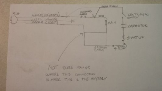
Here's a sketch of the wiring. It's crude, but should work as a sounding board.Wiring schematic.jpg
 
Ok well if it runs with the case grounded but no GFI then it's probably OK to use for as long as it lasts. It may fail soon if the leakage is high, more than 30-50 milliamp or so. If your meter measures AC amps/milliamps you could take a reading from the motor case to a good earth ground (like a water pipe)
The leakage is caused by either the windings and/or the start capacitor. There may also be a small amount from particles built up around the centrifugal switch (clean the area). You might have a hard time trying to find a replacement cap of that style, but you could mount an external cap instead.
Your sketch looks OK , the mystery connection is probably hidden in the windings somewhere by the factory.
Mark
ps the overload switch could also be leaky but not likely
 
Last edited:
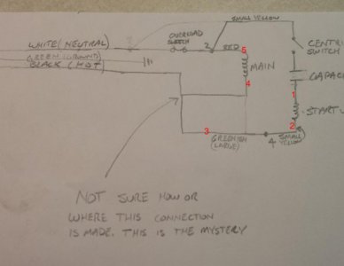
I don't understand. You say you have 5 wires coming from the windings but your diagram doesn't show that and your note says you don't know where the "mystery connection" is. Does that mean you really only have 3 wires actually coming from the windings?

I would NOT use the motor unless you can definitively determine there is no short to ground. The short may be internal to the flat metal capacitor in the base. Although these capacitors were relatively reliable they are now about 60 years old.

I added numbers to the diagram to show which ones lead to the stator windings.Motor Wire Diagram.jpg
 
All of these style motors that I have seen originally had a toggle switch mounted in the base. Could the extra wire be a remnant of the original switch? Is it maybe running into the base and not actually into the windings? It's been a while since I worked on one of these but if I remember correctly the run winding leads were colored red & green. Your ohmmeter is your friend.
 
I retested the start capacitor and it is clearly wasted. It's reading around 3 nanofarads. :( It was working before, so I tried to be very gentle with it during cleanup and painting.

I ordered a new capacitor, but now need to come up with a way to mount it. I couldn't find anything with the right specs that would fit in the base casting like the original. It's going to be a round 'can' type with spade connectors on one end.
 
Use the universal fastener - GE RTV clear silicone. This method has served me more times than I can mention.
 
I retested the start capacitor and it is clearly wasted. It's reading around 3 nanofarads. :( It was working before, so I tried to be very gentle with it during cleanup and painting.

I ordered a new capacitor, but now need to come up with a way to mount it. I couldn't find anything with the right specs that would fit in the base casting like the original. It's going to be a round 'can' type with spade connectors on one end.

That sounds strange. A reliable test I use for electrolytic capacitors is with an analog ohm meter set to Rx1K. I first connect the leads across the cap terminals to see the meter kick up towards infinite ohms and then reduce slowly, and then reverse the leads to do the same. If it performs as such in both directions - the cap is good. I do not trust some of the digital handheld cap measuring devices - although my Fluke seems to be reliable.
 
Back
Top