Craftsman Atlas 6x18 101.07301 Question

MotoJ

Registered
Registered
Joined
Feb 16, 2014
Messages
6
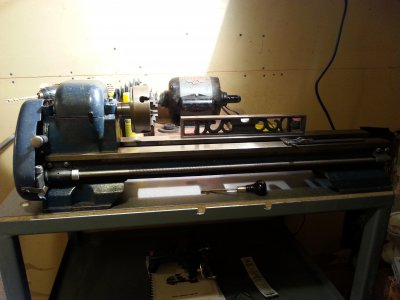
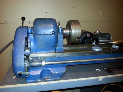
I recently acquired a Craftsman Atlas 101.07301 6"x18" lathe. It's my first machinist's lathe. I've really enjoyed perusing this site. This is my first post!


The previous owner had bought the lathe disassembled, in boxes. He managed to get it to about 80% complete, and lost interest. I've been trying to finish the job.


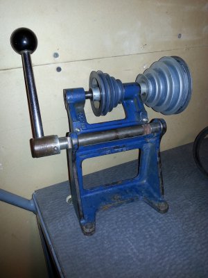
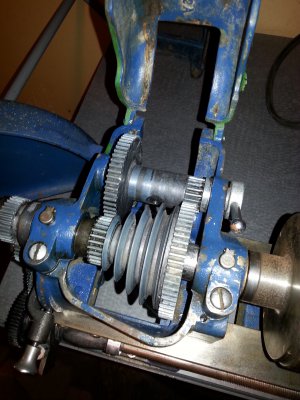
I wondered if anyone could explain to me, or furnish photos, of the countershaft configuration for my model. I just don't see how to adjust the two machine screws and jam nuts that provide tension to the drive belt. The lever is attached to a cross shaft that has two notches machined at either end, but inboard of the armature frame. Those machine screws engage the notched shaft somehow. I'm just not seeing it. It seems to me the top portion just flops over. I don't see how the lever returns it back upright.

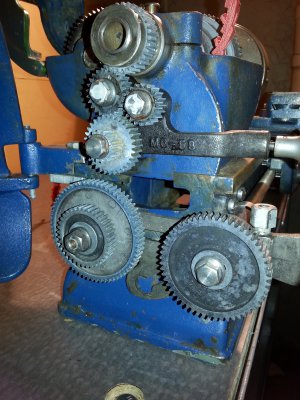
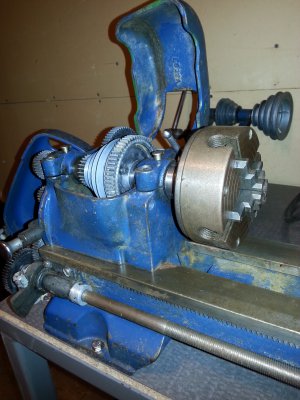
I know I'm missing some gears. I can see wear and indentations on the banjo lever that indicates there was another gear shaft attached. There are no gears to engage the lead screw. I had four or five extra gears in a bag. I suppose I have half a threading set or something.


Any help or advice anyone can give me would be much appreciated. I've attached some photos.


Thanks,
JD2014-02-22 20.15.20.jpg2014-02-22 20.14.34.jpg2014-02-22 17.53.35.jpg2014-02-22 15.29.09.jpg2014-02-22 20.15.48.jpg2014-02-22 20.16.24.jpg

2014-02-22 15.29.09.jpg 2014-02-22 17.53.35.jpg 2014-02-22 20.14.34.jpg 2014-02-22 20.15.20.jpg 2014-02-22 20.15.48.jpg 2014-02-22 20.16.24.jpg
 
MotoJ,

First thing that I think I see in your second photo is that what should be an M6-76 Rocker Shaft doesn't appear to have been made correctly. The right hand flat (machined across the shaft) is in line with the adjusting screw (as it should be). The left hand one is almost all inside of the bracket. It should be a little bit more than the width of the flat farther to the right, centered on the screw. Unless it's a trick photo, what you have will never work. Also, the 4-step pulley on the right end of the countershaft should be a 2-step, with the larger step closer to the bracket.

It will be a while before you have access to Downloads. If you'll send me your email address, I'll send you the parts manual on the 101.07301.

Robert D.

Thanks for the replies fellas. Robert, I think it's just that the shaft isn't slid in all the way. I need to install a pin in the other side to keep it from sliding back and forth. I just had it loose while I was fooling with it.

I did manage to figure out the bull gear/back gear dilemna I was having. Seems like that's a common problem.
Turns out the previous owner thought all the oilways were set screws, so everything was locked up. Plus someone was turning wood with this lathe, so there's sawdust gummed up in everything.

Yeah Chuck, you're absolutely right! Actually that's how I score most of my tools, bikes, cars, etc. Not sure how cost effective it is in the long run, though!
 
OK. I hope that you're right. The left end (right end in your photo) of the rocker shaft should have a 1/8" x 1" cotter pin through it.

Robert D.
 
MotoJ,
Here is my input. If the owner dismantled this and started reassembly, he probably had no documentation on how the parts went together. Looking at that rocker shaft, it is might be possible that the handle is installed on the wrong end. There are holes in both ends, one uses a cotter pin and the other uses a roll pin I believe they are the same diameter. The rocker shaft can be put in from either direction, the handle can mount on either end, I think. I went through a similar process after having my 6" lathe apart for almost 20 years. Someone did some drilling which made it more confusing. Not an expert here but, might be worth investigating.
Also, check out this website: http://vintagemachinery.org/home.aspx
There is a manual for your lathe but, there is no exploeded view, just and assemblage of the parts. I would suggest looking at the 101.21400 publication (pdf). Not exact but any help is better than none.
The bracket can feasibly be mounted in 2 directions and the rocker shaft and spindle can be also. I turned my bracket around for ease of mounting the motor on my table. If using 3/8" belts (3L), McMaster-Carr has a huge selection of lengths and priced very reasonable.
These are fantastic small lathes. Good luck and keep posting.
Paul

PS, I used to live in Baltimore - Gardenville
 
Last edited:
Back
Top