Cutting a simulated curved groove. Confirmation of formula for head tilt angle.

Parlo

Registered
Registered
Joined
Feb 21, 2022
Messages
786
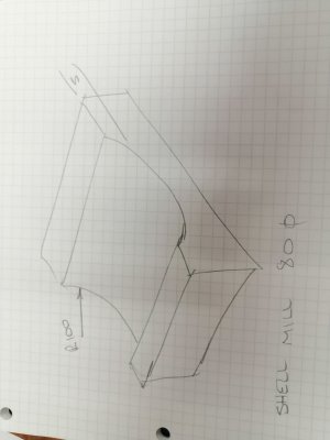
My plan is to cut a curved groove by tilting the head of my mill.
The groove is 100mm radius and 5mm deep.
My cutter is 80mm diameter.
I calculate the groove width will be 62.45mm @ 5mm deep.

The formula that I have seen is:
Sin of the head tilt angle = Cutter diameter divided by the required radius.
This seems a bit general as it does not have a reference to the depth.
However, I get 23.57 degrees using this formula.
This angle will give the correct width at 6mm deep - 1mm too deep!
At the correct depth it gives a width of 58.1mm - about 4mm too narrow.

My calcs give an angle of 19.47 degrees to give the correct width at the correct depth.

Has anyone had experience with using this standard formula?
Am I using the wrong formula?
Are my calcs wrong?

Thanks.
 
I am trying to picture in my head. Are you cutting a groove in a cylinder? internal groove? face groove? Helical? Axial? The cutter is 80 mm diameter but what type of cutting tool? Fly cutter?
You may need to do test pieces to get the proper dimensions
A little over my pay grade without a drawing or sketch.
Martin
Here is a sketch.
 

Attachments

  • radius groove.jpg
    radius groove.jpg
    113.1 KB · Views: 34
tilting a round cutter at an angle will cut an ellipse NOT a circle. I submit that is the source of your error.
Thanks, the title states that it is a simulated curve.
There is an angle that will cut a curve to pass through the 2 top points and centre point that a 100mm radius will generate at 5mm deep.
I can't get the standard formiula to acheive this.
 
A curve is a curve, but a circular curve is different from an ellipse.

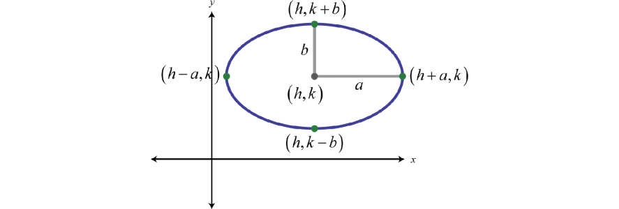
download (1).png
I'm pretty sure you can work out the sin(d1-d2) for your mill head angle The angle locks the foci, so plotting the perimeter path is just a matter of algebra once you know the cutter radius, head angle, and desired cut depth:

{[(x−h)^2]/a^2}+{[(y−k)^2]/b2}=1

download (2).png
 
I experimented with making shallow mirrors by doing something similar to what you describe. To get the circular symmetry I put my workpiece in my rotary table and turned it while milling. Instead of tilting the column I tilted the RT a few degrees. It worked pretty much as expected. The result was a patch of an oblate spheroid, which is what you get when rotating an ellipse.

The proto-mirror only was about 1" in diameter, limited by the size of the end mill I used. A fly cutter could be used to scale it up. I never took it that far though.

To get a true circular channel you would have to use a ball end mill. Its shape is invariant relative to tilt angle, but for large channels you'd be limited by the size availability (not to mention cost) for larger ball-end mills. If you've got a CNC machine that would do the job, although it might take a lot of passes to achieve the desired match to a circular section.
 
A curve is a curve, but a circular curve is different from an ellipse.

View attachment 451444
I'm pretty sure you can work out the sin(d1-d2) for your mill head angle The angle locks the foci, so plotting the perimeter path is just a matter of algebra once you know the cutter radius, head angle, and desired cut depth:

{[(x−h)^2]/a^2}+{[(y−k)^2]/b2}=1

View attachment 451445
Thanks for the details. I have not seen Sin(d1-d2) anywhere and not that format. Sin(100 - 80 ) = 0.342 ?

I found this formula - Sin of head angle = Cutter radius divided by workpiece radius which gave 23.58 degrees which was not good enough. As I explained it does not generate an ellipse that will pass through the 3 points on the arc I want to simulate.

The angle I calculate is 19.47 degrees that should generate the elliptical curve I need.

Is the formula I find on the web correct - a poor approximation or have I used the formula wrong.?
 
I have posted about this before, referring to it as "faking a radius". The handwritten note that Fred gave me says "Dia of Radius to be cut Divided into Dia. of Cutter=Sine of Angle" followed by "Cutter must be smaller than Dia of Radius to be cut"

I understand this to mean cutter diameter divided by arc diameter.

I used this once many years ago. It was adequate for the situation.
 
I experimented with making shallow mirrors by doing something similar to what you describe. To get the circular symmetry I put my workpiece in my rotary table and turned it while milling. Instead of tilting the column I tilted the RT a few degrees. It worked pretty much as expected. The result was a patch of an oblate spheroid, which is what you get when rotating an ellipse.

The proto-mirror only was about 1" in diameter, limited by the size of the end mill I used. A fly cutter could be used to scale it up. I never took it that far though.

To get a true circular channel you would have to use a ball end mill. Its shape is invariant relative to tilt angle, but for large channels you'd be limited by the size availability (not to mention cost) for larger ball-end mills. If you've got a CNC machine that would do the job, although it might take a lot of passes to achieve the desired match to a circular section.
Thanks, I don't need a true circular channel, I need an approximate circular channel where the elliptical arc passes through the two ends and the midpoint of a 100mm radius arc 5mm deep.
I don't fancy buying a 200mm ball end mill.
 
Back
Top