- Joined
- Jan 25, 2015
- Messages
- 2,558
Hello.
I'm not sure if this is a "beginners" question, but here goes:
I'm building a chain drive for what was a CVT (IE: snowmobile clutch) driven transmission.
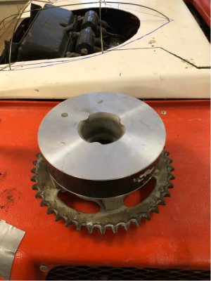
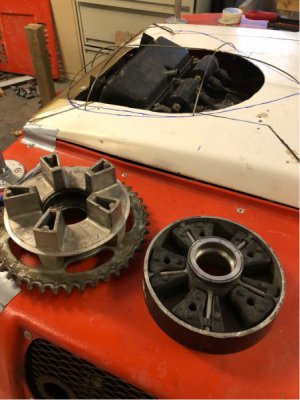
I've turned the center section out of an aluminum wheel (CBR600RR) to get the sprocket carrier and retain the "cush drive" (functions as a damper for vibes and shock loading):


I cleaned up the center bore to be dimensional true and it works out to 2.136 - 2.137".
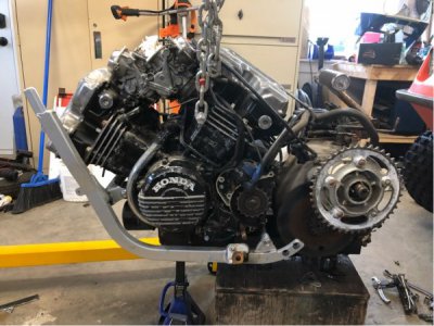
The transmission input shaft is 1" OD:

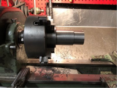
So I'm machining an "adapter" to go from the hub bore to the transmission input shaft. The adapter is mild steel (1018 IIRC):

The hub goes on the middle "step" of the adapter. The smaller diameter is for the sprocket carrier and is a slip fit as there will be another piece that will secure it into the cush drive hub. It's got a few thou clearance as the sprocket carrier needs to "float" a bit to "self align" and absorb drive line loads.
The transmission input shaft is keyed, so retention and handling the power there is a fairly simple matter.
The hub to the adapter is a different story though. The Aluminum hub does not have enough "meat" in order to incorporate a keyway and there is also no suitable place where I can add a pin or bolt to mechanically lock the hub and adapter together.
So, from what I can deduce, I'm left with doing an interference fit.
What's a bit above my pay grade is calculating how much of a friction fit I need.
I plan to use heat to get my fit. Right now, the adapter shoulder is 0.091" larger than the bore in the cush drive hub. I stopped there in order to work out what I need for a final dimension as an interference fit.
The hub is (essentially) a cast aluminum piece, the adapter is mild steel. The final dimension is right around 2.137".
I took the hub and heated it to 450C and the clearance opened up to 2.141-2.142", so it gains about 0.004-0.005 when heated.
The joint needs to hold around 40-50 ft/lbs of torque at most and there's just a bit over 3" of shaft and hub length in contact once assembled.
Once assembled, it will never have to come apart again.
It seems that an interference fit on a drive component is "usually" around 0.004-0.005" in this type of assembly, although the actual calculation of the needed dimension is just outside of my knowledge level.
Any ideas on where I shoudl be shooting for on dimensions?
If it was all steel, it would be an easy fix; a bead of weld from the mig and done.....
I'm not sure if this is a "beginners" question, but here goes:
I'm building a chain drive for what was a CVT (IE: snowmobile clutch) driven transmission.
I've turned the center section out of an aluminum wheel (CBR600RR) to get the sprocket carrier and retain the "cush drive" (functions as a damper for vibes and shock loading):


I cleaned up the center bore to be dimensional true and it works out to 2.136 - 2.137".
The transmission input shaft is 1" OD:

So I'm machining an "adapter" to go from the hub bore to the transmission input shaft. The adapter is mild steel (1018 IIRC):

The hub goes on the middle "step" of the adapter. The smaller diameter is for the sprocket carrier and is a slip fit as there will be another piece that will secure it into the cush drive hub. It's got a few thou clearance as the sprocket carrier needs to "float" a bit to "self align" and absorb drive line loads.
The transmission input shaft is keyed, so retention and handling the power there is a fairly simple matter.
The hub to the adapter is a different story though. The Aluminum hub does not have enough "meat" in order to incorporate a keyway and there is also no suitable place where I can add a pin or bolt to mechanically lock the hub and adapter together.
So, from what I can deduce, I'm left with doing an interference fit.
What's a bit above my pay grade is calculating how much of a friction fit I need.
I plan to use heat to get my fit. Right now, the adapter shoulder is 0.091" larger than the bore in the cush drive hub. I stopped there in order to work out what I need for a final dimension as an interference fit.
The hub is (essentially) a cast aluminum piece, the adapter is mild steel. The final dimension is right around 2.137".
I took the hub and heated it to 450C and the clearance opened up to 2.141-2.142", so it gains about 0.004-0.005 when heated.
The joint needs to hold around 40-50 ft/lbs of torque at most and there's just a bit over 3" of shaft and hub length in contact once assembled.
Once assembled, it will never have to come apart again.
It seems that an interference fit on a drive component is "usually" around 0.004-0.005" in this type of assembly, although the actual calculation of the needed dimension is just outside of my knowledge level.
Any ideas on where I shoudl be shooting for on dimensions?
If it was all steel, it would be an easy fix; a bead of weld from the mig and done.....

