Design help needed for clutch system

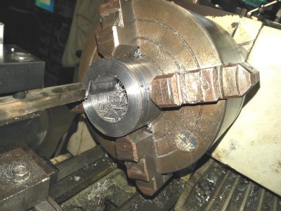
I started making the keyway with a narrow cutter but that became very tedious so I changed to an 8mm wide.
cutting keyway 2.jpg
Sliding the carriage back and forth untill I got it 3mm deep, So little was removed on each stroke it took 2 afternoons.
I checked it on the spindle and it was a perfect fit. BUT two days and rust started forming inside, gah!
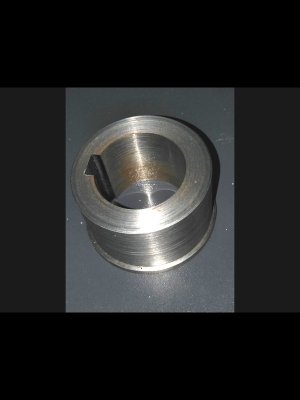
keyed hub.jpg
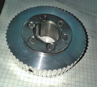
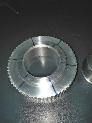
Then I bored out the cogged pulley to fit, that was way easier.
gog pulley1.jpg

full pulley.jpg
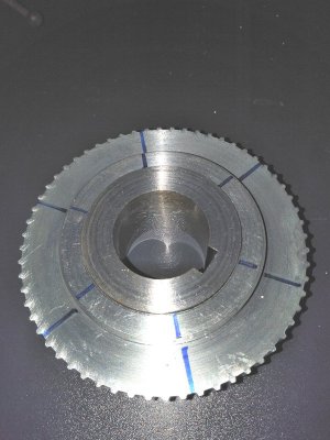
Now I have to drill six 3/16" holes for the balls where the blue lines are then drill 5mm and tap M6x1 for the grub screws and springs.
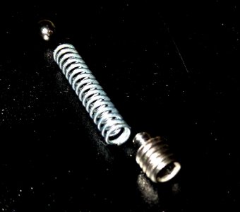
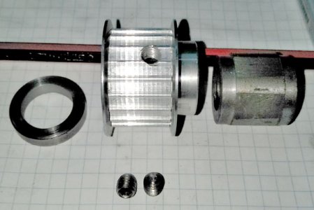
spring1.jpg
I turned a little spigot to centre the spring on the grub screw.
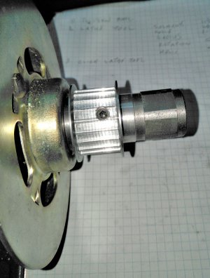
I made a quick test piece to check the spring pressure and if the ball would rise and slip.
At the highest pressure it was immovable, at the lowest it was difficult but did slip.
appologies for the crap photos as I'm coming to grips with a new image processing program.

edit - I forgot to mention the chuck was locked when broaching the keyway.
 
Last edited:
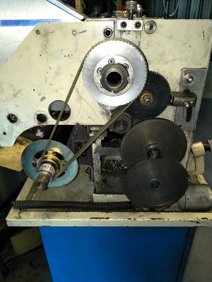
I'm in the process of modifying a dc treadmill motor to fit my 9x20 lathe.
The main reason for this to get an easier variable speed system to replace the belts. (it was free)
As it will be a 3:1 reduction from the motor to the spindle using cogged pulleys and belt I feel some sort of clutch would be a good idea in case of a crash. (I have been known to be clumsy in the past)
I'm thinking of a steel hub with detants drilled around its circumference, 6 equidistant drilled and tapped holes radially around the cog and using balls and springs tensioned with grub screws with the balls engaging in the detants in the steel hub.
Similar in operation to the original clutch but in a different orientation.
The aluminium cogged pulley will sit on the steel hub with a bearing fit, ie, it will turn but no play.
My questions are
Will this work?
If not why not?
Is 6 balls enough?
What would be the best number of balls?
Thanks.

Look at that clutch design
 
I remember that and thought it was very elegant, I've been following Martins marble machine builds from the first one.
I also like the bands music.
 
I remember that and thought it was very elegant, I've been following Martins marble machine builds from the first one.
I also like the bands music.

Same here. Watching him constantly undo his work is maddening but he has an awesome result to show for it.
 
And the motor in place
l_mounted.jpg

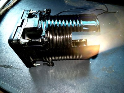
I decided to use a computer fan for cooling and needed to make a round into a square bit of ducting.
I found this on line and thought excellent, way to go.
Then I thought again and used a hammer and an empty can of doggie chow and made this
l_shroud.jpg
The cutouts are where the brushes stick out from the motor
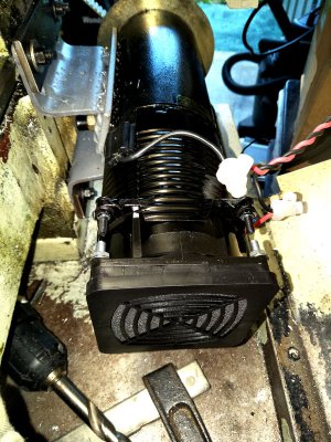
l_on-motor.jpg
Its held to the motor with a worm drive clip and is solid.
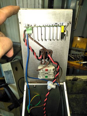
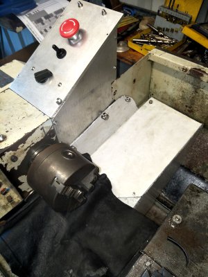
As luck would have it I had two triangular bits of ally plate that were the exact size to make the extended control box
to hold the switches and speed controller.
l_inside.jpg
The lid hinges and is closed with knurled screws for ease of access.
I also added more shrouds to cover the motor leaving a little gap at the bottom for air flow.
The fan is always on when there is power to the lathe.
I am most impressed with the use of variable speed
l_outside.jpg
 
update
the motor stalled when I was parting 1.5mm dia aluminium bar.
I guess I have to slacken the screws to the clutch balls a bit.
Once it stalled there was an almighty bang but no smoke.
The glass fuse on the circuit board had exploded, the mosfet had fried and the bridge rectifier had karked it.
They were removed and replaced with larger value ones, I used the aluminium switch housing as the new heat sinks as theres plenty of mass there.
Added a 400V 1000uf cap across the output.
Added a 15A re-setable circuit breaker in place of the 20A glass fuse.
The motor runs as smooth as silk now except at very slow speed where its a little rougher.
I stalled it again but this time it tripped the 10A re-settable on the extension plug board.
Today I will re-set the friction clutch to a weaker setting.
No photos as too busy/lazy to take them.
 
Damn, what a polymath!
Machining, cooking, astronomy and also electronics.

Charles, if I ever grow up I want to be like you!

-brino
 
An elegant and sophisticated solution....
 
Thanks Brino but my knowledge of electronics can be written on a mozzies bum with a felt tip pen.
I cant read a circuit, very very limited understanding of what the components do, I just replaced the ones that looked damaged with higher rated ones.
Pretty good cook though :laughing:
 
Back
Top