Diy Touchdro using esp32

Awesome yuriy
i didn’t write the sketch …. thanks for your detailed analysis

it was found while looking for a way to add dro to my lathe (after you had mentioned esp32) and (thankfully) now that you have published your diy esp32 it is the way forward for me. Waiting and watching for diy release in November

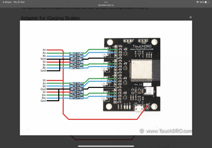
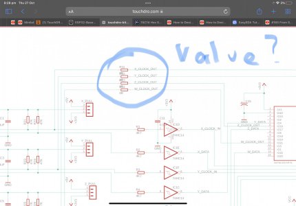
any update on why/how your published diagram of adding level shifters doesnt show connection to 3v line?

again thanks for your awesome work

cheers jeff
Jeff,
Which diagram are you referring to?
Thank you
Yuriy
 

Attachments

  • 3AD7D292-3534-49ED-BE74-1FCD9A3A848F.png
    3AD7D292-3534-49ED-BE74-1FCD9A3A848F.png
    1.6 MB · Views: 142
Hi yuriy referring to your diy schematic what are the values of r11-r14 on clk out lines

thanks jeff
busy trying to climb another learning curve mountain as I dive into schematic to pcb software so I can make a pcb
 

Attachments

  • 215495C1-0B52-4786-A489-B0897E06F8D1.jpeg
    215495C1-0B52-4786-A489-B0897E06F8D1.jpeg
    226.5 KB · Views: 136
Hi yuriy referring to your diy schematic what are the values of r11-r14 on clk out lines

thanks jeff
busy trying to climb another learning curve mountain as I dive into schematic to pcb software so I can make a pcb
For the voltage shifters just connect LV to any scale Vcc output. I skipped those thinking that it will be obvious, but many people get confused. I need to redo the graphic.

R11-R14 are optional jumpers used to connect clock for iGaging 21-bit scales. For glass scales and Shahe "Linear Remote DRO" scales those are not needed.

Regards
Yuriy
 
Hi Yuri,
i plan to take DIY route as taxes and shipping costs are killing economical sense for buying:/ i can see that your ESP32 kit is using different schematic diagram from the one showed on your website. You are using 26LS32 differential line drivers for X/Y/Z/A axes and one more mysterious chip. What is it? Are you ok to share schematic diagram for this version? Thanks for reply.
 
Back
Top