Drilling head of Round Column Mill

slow-poke

Registered
Registered
Joined
Dec 9, 2016
Messages
303
I'm thinking about adding a linear bearing to preserve alignment on my round column mill.

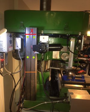
I have a stout piece of 2x4 rectangular tubing (see image), I will need to shave a couple of inches off the overall length and then cut it in roughly the center.

For mounting the bottom half, I can mill a rectangular block that will be bolted to the base and fit snugly inside the tube, the tube can then be bolted to the block.

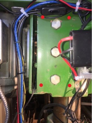
For mounting the upper half I will need to drill and tap the head (probably 4 places) two on either side of the three large bolts (see 2nd image)

I would think there is a fair bit of stress in the head, and I want to make sure I'm not introducing an oportunity for a stress crack to occur in the head as a result of the four additional holes I will add.

Thoughts on drilling the head? Yes, no, if yes what size bolts or studs, I'm thinking smaller is better, perhaps 4 x 1/4", or perhaps 4 x5/16"


Once the two pieces are mounted I will mount a linear bearing, or possible a pair in parallel on the wide face of the rectangular tube, perhaps something like this:

Note the head is in the lowest position in the image. The linear bearings will straddle the cut (orange line).
 

Attachments

  • IMG_0086.JPG
    IMG_0086.JPG
    109.3 KB · Views: 109
  • IMG_0088.jpg
    IMG_0088.jpg
    70.1 KB · Views: 98
Last edited:
Looks like a good project, some one else used a solid round ground 1" bar.
 
My RF clone is essentially the same as your mill. The casting where you intend to drill and tap is substantial. You should have no problems regarding stress cracking.
 
Interesting idea - a couple of thoughts:

- I agree that the casting of the head is substantial and stress cracking should not be an issue. If this is performing the way I think it should the forces on the connections should not be super great.
- How does the linear rail and bearings attach - to the vertical steel tube?
- How do you keep the vertical steel tube aligned if it is only connected at the bottom? A small deflection on that will reduce the accuracy of the system.

I will be posting a different, and much crazier, "solution" to keeping the X in a day or two. It involves a linear rail about identical to the one you linked to but in a very different way. Stay tuned!
 
Here is the thread I started on my nutty "solution" for keeping the x...

 
Interesting idea - a couple of thoughts:

- I agree that the casting of the head is substantial and stress cracking should not be an issue. If this is performing the way I think it should the forces on the connections should not be super great.
- How does the linear rail and bearings attach - to the vertical steel tube?
- How do you keep the vertical steel tube aligned if it is only connected at the bottom? A small deflection on that will reduce the accuracy of the system.

I will be posting a different, and much crazier, "solution" to keeping the X in a day or two. It involves a linear rail about identical to the one you linked to but in a very different way. Stay tuned!
See image above:
+ I have already cut off above the red line (tube was too long)
+ Eventually the tube will be severed at the orange line.
The vertical rectangular tube will be cut into two halves (top and bottom), top to the head, and bottom to the base.
The rod(s) will straddle the two halves, fixed on the bottom (two points) and two linear bearings attached to the head. With the head all the way down the two rectangular tubes touch at the orange line, and as you raise the head the two two rectangular tubes separate at the orange line with the rods being the bridge between the top and bottom half.

Typically these linear bearing kits come as a pair, so I might just mount them side by side for less flex. My one concern is, how rigid are these Amazon special type linear bearing kits? For now I’m just going to focus on getting the rectangular tube(s) mounted parallel to the column. Nether mounting surface is machined, so this might prove to be a bit tricky.

Your laser idea is really clever. Half the fun is taking these what start out as “what if” thoughts rolling around in our brains and then actually realizing them. I totally get it.
 
Last edited:
See image above:
+ I have already cut off above the red line (tube was too long)
+ Eventually the tube will be severed at the orange line.
The vertical rectangular tube will be cut into two halves (top and bottom), top to the head, and bottom to the base.
The rod(s) will straddle the two halves, fixed on the bottom (two points) and two linear bearings attached to the head. With the head all the way down the two rectangular tubes touch at the orange line, and as you raise the head the two two rectangular tubes separate at the orange line with the rods being the bridge between the top and bottom half.

Typically these linear bearing kits come as a pair, so I might just mount them side by side for less flex
Ahh - I see. I look forward to seeing how this turns out as I already have some of those linear rails (see link to my post). I am getting within 0.002" with my laser system as of now.
 
Ahh - I see. I look forward to seeing how this turns out as I already have some of those linear rails (see link to my post). I am getting within 0.002" with my laser system as of now.
Tomzo,
I will let you know when it’s together, I will be thrilled if my contraption gets me within 0.002“ Thinking about your solution after raising the head how do you get the target in the correct position vertically, I guess simply by looking at the dot on the target and tweaking the motor slightly?
 
Last edited:
Tomzo,
I will let you know when it’s together, I will be thrilled if my contraption gets me within 0.002“ Thinking about your solution after raising the head how do you get the target in the correct position vertically, I guess simply by looking at the dot on the target and tweaking the motor slightly?
Yes - I have to bump it up and down a few times to get it aligned. If I am off a bit it will not light up as I sweep across the sensor hole with the laser. If I am off vertically by a mm or so I won't get any signal in the detector. I considered using a stepper motor so I could make more precise movements but this seems to work. As someone else mentioned it is a Rube Goldberg way to go about it.
 
Back
Top