- Joined
- Nov 11, 2017
- Messages
- 77
Here’s a project that I just finished up for my Grizzly G0752 lathe. It’s a digital readout for the angle of the compound. The original angle indicator scale on my G0752 lathe was off by about 3 degrees and was difficult to see so I often resorted to using a digital protractor to set the compound angle. Using the digital protractor is awkward since there isn’t a good set of surfaces to set the protractor against and it seems like it takes three (or more) hands to hold the protractor, move the compound, and tighten the lock nuts.
I thought it would be nice to have a digital readout for the compound angle but my searches didn’t turn up anything that could be cleanly integrated into my lathe. There are many kinds of angle sensors and encoders but they are either very large and/or expensive. My search turned up an interesting sensor from AMS (AS5147P) that uses a magnet and a sensor chip that interprets the angular position of the magnet to within .087 degrees. The things I like about this technology are that it is non-contact, zero backlash, small, and inexpensive. The drawbacks are that it requires some modification to the cross slide and compound and that it requires an Arduino and software to make it all work. OK, this last one wasn’t really a drawback since I’ve been looking for a good excuse to learn to write software for Arduino and this was a great first project for doing that.
The compound on the G0752 (and G0602) rotates on a post that sticks down into a hole on the cross slide. I installed the magnet inside the bottom end of the post and the circuit board with the sensor chip is attached to the underside of the cross slide just below the magnet. This required pocketing out the compound pivot post for the magnet, pocketing out the underside of the cross slide for the circuit board, and a relief notch on the side of the cross slide leadscrew nut for cable routing.
As the compound rotates the sensor detects the angle of the magnet and reports it to an Arduino which then does some math and displays the angle on the display as 000.0 to 180.0 degrees in either direction from the zero. The sensor divides one revolution into 4096 steps which is about .087 degrees of resolution. That’ll do.
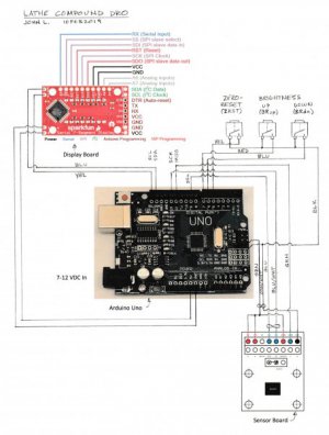
The Arduino Uno microcontroller is in a small plastic box mounted to the backsplash. The plastic box also includes the display, a zero-reset button and two buttons for brightness control. The display brightness controls aren’t really required since brightness can be set in software but I added the buttons just because. The software also stores the last zero position in memory so it will display the correct angle even after a power cycle.
When you press the zero-reset button the display reads 000.0 and any rotation of the compound in either direction from zero is displayed but there is no negative sign. I decided not to display negative angles partly because this display doesn’t have room for a minus sign and I’ve found that it’s not too hard to remember which direction I’ve rotated the compound. I also printed a faceplate for the display box using the 3D printer at work and painted it to match the backsplash.
This project stretched my abilities as I ran into a number of challenges along the way. It was a lot of work for the benefit but I find that it’s a useful addition to my lathe.
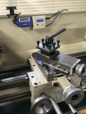 < The completed DRO displaying 29.5 degrees.
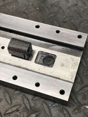
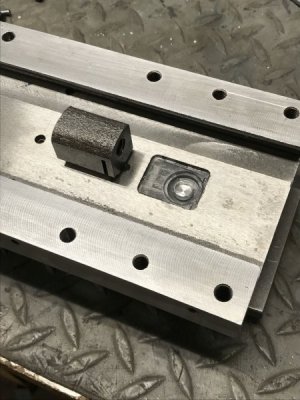 < Pocket for the circuit board and plastic insulator.
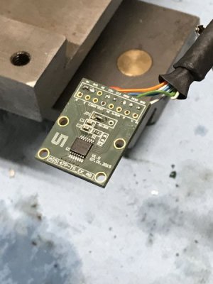
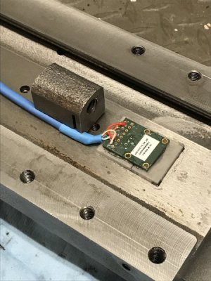 < The sensor board. (The right photo is prior to pocketing.)
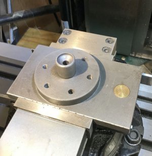 < Machining out the post to keep iron away from the magnet.
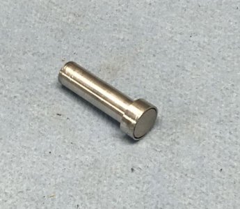 < The aluminum holder for the magnet.
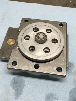 < Magnet installed in the end of the compound post.
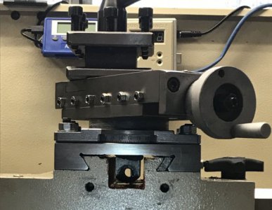 < A view with the cross slide screw removed showing tight clearances.
If there's interest, I'll post the parts list, build notes, and software later.
I thought it would be nice to have a digital readout for the compound angle but my searches didn’t turn up anything that could be cleanly integrated into my lathe. There are many kinds of angle sensors and encoders but they are either very large and/or expensive. My search turned up an interesting sensor from AMS (AS5147P) that uses a magnet and a sensor chip that interprets the angular position of the magnet to within .087 degrees. The things I like about this technology are that it is non-contact, zero backlash, small, and inexpensive. The drawbacks are that it requires some modification to the cross slide and compound and that it requires an Arduino and software to make it all work. OK, this last one wasn’t really a drawback since I’ve been looking for a good excuse to learn to write software for Arduino and this was a great first project for doing that.
The compound on the G0752 (and G0602) rotates on a post that sticks down into a hole on the cross slide. I installed the magnet inside the bottom end of the post and the circuit board with the sensor chip is attached to the underside of the cross slide just below the magnet. This required pocketing out the compound pivot post for the magnet, pocketing out the underside of the cross slide for the circuit board, and a relief notch on the side of the cross slide leadscrew nut for cable routing.
As the compound rotates the sensor detects the angle of the magnet and reports it to an Arduino which then does some math and displays the angle on the display as 000.0 to 180.0 degrees in either direction from the zero. The sensor divides one revolution into 4096 steps which is about .087 degrees of resolution. That’ll do.
The Arduino Uno microcontroller is in a small plastic box mounted to the backsplash. The plastic box also includes the display, a zero-reset button and two buttons for brightness control. The display brightness controls aren’t really required since brightness can be set in software but I added the buttons just because. The software also stores the last zero position in memory so it will display the correct angle even after a power cycle.
When you press the zero-reset button the display reads 000.0 and any rotation of the compound in either direction from zero is displayed but there is no negative sign. I decided not to display negative angles partly because this display doesn’t have room for a minus sign and I’ve found that it’s not too hard to remember which direction I’ve rotated the compound. I also printed a faceplate for the display box using the 3D printer at work and painted it to match the backsplash.
This project stretched my abilities as I ran into a number of challenges along the way. It was a lot of work for the benefit but I find that it’s a useful addition to my lathe.
 < The completed DRO displaying 29.5 degrees.
 < Pocket for the circuit board and plastic insulator.
 < The sensor board. (The right photo is prior to pocketing.)
 < Machining out the post to keep iron away from the magnet.
 < The aluminum holder for the magnet.
 < Magnet installed in the end of the compound post.
 < A view with the cross slide screw removed showing tight clearances.
If there's interest, I'll post the parts list, build notes, and software later.


