DRO Install on a 1340 GT

1silica

Registered
Registered
Joined
May 25, 2019
Messages
11
I purchased a DRO along with my 1340GT from PM. In hindsight it might have been a good idea to pay the extra and have them install the DRO. Instead I spent the extra money on tooling and a drill chuck. Not I'm facing an install with no instructions :)

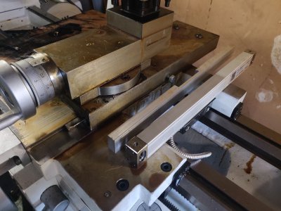
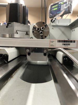
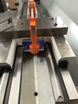
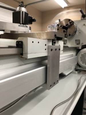
For those of you who have a 1340 (or equivalent) and a DRO installed, do you recommend the scale be mounted on the headstock or tailstock side of the tool carriage? I'm inclined to remove the carriage then drill and tap a pair of holes in the tailstock side, use a piece of aluminum stock to make a standoff to mount the scale to and still allow access to the gib screw. I'd love to hear thoughts on which side to install the DRO.

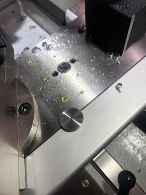
Also is that single screw on the adjustable gib meant to lock the carriage travel or take out the play? If I'm drilling and tapping on that side anyway is there anything to be gained by adding a few more tensioning screws for this gib? Thanks in advance for any replies.
 

Attachments

  • IMG_20200816_145201.jpg
    IMG_20200816_145201.jpg
    5 MB · Views: 329
I installed mine on the tail stock side and installed a hex bolt to tighten the compound.

I made a cover with slotted screws holes to allow access to the hex bolt and it covers the cutout when not needed.

Things to watch for, when drilling into the compound make sure there's nothing important that you will hit or interfere with.

You will need an extended drill bit to drill the casting to mount the read head, I removed the tail stock and drilled with a home made extension,

Take your time and have fun, it can be stressful but very rewarding when finished.

David.
 

Attachments

  • IMG_2112.JPG
    IMG_2112.JPG
    1.2 MB · Views: 342
  • IMG_2108.JPG
    IMG_2108.JPG
    1.2 MB · Views: 321
  • IMG_2228.JPG
    IMG_2228.JPG
    1.1 MB · Views: 317
  • IMG_2096.JPG
    IMG_2096.JPG
    1.2 MB · Views: 309
Be aware that the front of the tailstock can bump the read head on the cross slide scale. When using geometric die head to bump cross slide (causing the head to open and stop cutting threads) ,I found it could hit the head of scales.
I have found the single tensioning screw holds it tight enough and tightening more screws is that much more effort and time.
 
I installed my cross slide scale on the tailstock side of the carriage on a standoff to give access to the carriage lock hex-bolt.

IMG_5656.jpeg


The scale faces downward:

IMG_5677.jpeg


I provisioned the mounting system for a protective cover on the tail stock end:

IMG_5684.jpeg


Also provisioned the bracket to have a stainless steel sliding cover and I made two low profile knurled/threaded knobs to lock the cover closed:

IMG_5745.jpeg


Cover closed position:

IMG_6389.jpeg


Once complete, I disassembled everything and had all the brackets hard anodized:

IMG_6387.jpeg


On the Z-axis, I also made custom brackets and employed a drag chain for the encoder cables and Fogbuster coolant supply lines:

IMG_6402.jpeg


IMG_6425.jpeg


Full build is documented here across three pages: https://flic.kr/s/aHskYxDKzN
 
Simply gorgeous work, wow! Thank you for sharing. I have glass scales so it seems smart to keep the open side facing down. I really like your very elegant sliding cover.
 
I installed mine on the tail stock side and installed a hex bolt to tighten the compound.

I made a cover with slotted screws holes to allow access to the hex bolt and it covers the cutout when not needed.

Things to watch for, when drilling into the compound make sure there's nothing important that you will hit or interfere with.

You will need an extended drill bit to drill the casting to mount the read head, I removed the tail stock and drilled with a home made extension,

Take your time and have fun, it can be stressful but very rewarding when finished.

David.

Thank you for posting this. It's very helpful. I'd like to ask about how you attached your scale. My glass scale would have me drilling and tapping holes in the compound right about where the retaining screws for the gib sit and the casting is relatively thin because of the large hole. I'm thinking of bolting an AL spacer to the compound with mounting holes set closer together so they don't interfere with the gib retaining screw holes. I would then need a second set of tapped holes in the spacer set farther apart to position the scale. Thoughts?
 
Thank you for posting this. It's very helpful. I'd like to ask about how you attached your scale. My glass scale would have me drilling and tapping holes in the compound right about where the retaining screws for the gib sit and the casting is relatively thin because of the large hole. I'm thinking of bolting an AL spacer to the compound with mounting holes set closer together so they don't interfere with the gib retaining screw holes. I would then need a second set of tapped holes in the spacer set farther apart to position the scale. Thoughts?

When I installed the scale I used a piece of aluminum to space out the scale, I used 5mm screws to hold the aluminum bar.

The scale came with a thin mounting bracket which I copied but I should have just drilled my own mounting holes as they were not in a great place.
I remember that I drilled a bit close to the large hole in the cross slide and needed to cut one of the mounting screws down a bit so it didn't interfere with the bolts from the compound. Not sure if I hit the gibs or not but no issues with anything.

If you want I can remove my scale and get more detailed pictures if you need, it will only take a few minutes, so just ask.

I did think about removing the compound and cross slide before drilling to check it out but it's more work than I was prepared for at the time, so just got it done and it worked out fine.

David.

There are a few more photos here in my post about mounting the DRO, also details on how I mounted my display.
 
Last edited:
Thank you for posting this. It's very helpful. I'd like to ask about how you attached your scale. My glass scale would have me drilling and tapping holes in the compound right about where the retaining screws for the gib sit and the casting is relatively thin because of the large hole. I'm thinking of bolting an AL spacer to the compound with mounting holes set closer together so they don't interfere with the gib retaining screw holes. I would then need a second set of tapped holes in the spacer set farther apart to position the scale. Thoughts?
You're welcome - I hope it's useful. And thanks for the feedback.

With respect to your question, do you mean "compound" or "cross slide". I assume you mean cross slide - putting a DRO on the compound sounds like a fools errand to me.

So assuming you mean cross slide, what you suggest is pretty much what I did. Have a look at this photo - these are all the custom brackets I made for the 1340 upgrades when they came back from the anodizing shop. Look at the L-bracket outlined in red:

IMG_6202.jpeg


That is the bracket that holds the scale and attaches to the side of the cross slide. It bolts in 4 positions with locations chosen specifically to not be in the area where the gib adjustment screw is located. Also note that instead of putting the bracket on a stand-off, I simply machined a window into the bracket for access to the cross slide locking bolt. As delivered, that locking screw is socket-head hex-cap screw, and I replaced it with a hex-head bolt that was just long enough to lock down the cross slide, but not so long that it sticks way out past the side of the cross slide when loosened. This way a hex spanner (wrench) from above can lock the cross slide with a simple 90-degree rotation of the bolt.

This is the hex-head bolt that substitutes for the screw supplied with the lathe for locking the cross slide:

screenshot_3886.jpg


And this is the low profile wrench that actuates that screw through the window in the L-bracket:

screenshot_3887.jpg


Now look at the following two images. I have marked the screws that mount the bracket to the cross slide in blue, the green circles are the threaded holes that receive the two screws that hold the scale to the underside of the bracket, and the two red stars are the threaded holes for the knurled knobs that secure the stainless steel cover that slides back and forth over the access window in the bracket. In the first photo, you can also see the hex-bolt that locks the cross slide, as well as how I mounted the encoder (reader) to the apron with another L-bracket.

IMG_5659.jpeg


IMG_5655.jpeg


Here's a view from the top showing the access to the cross slide locking bolt:

IMG_5658.jpeg


This shows the scale mounted to the underside of the bracket via the two screws into the green-circled threaded holes:

IMG_5672.jpeg


And here is the protective end-plate cover that protects things from the tailstock:

IMG_5684.jpeg


The sliding cover in place:

IMG_5745.jpeg


The knurled knobs I made to lock the cover:

IMG_5729.jpeg


And if you do a sliding cover, be mindful that whatever secures it in place doesn't block the base of the compound from rotating:

IMG_5747.jpeg


Hope this helps. Please post photos of what you come up with.
 
Back
Top