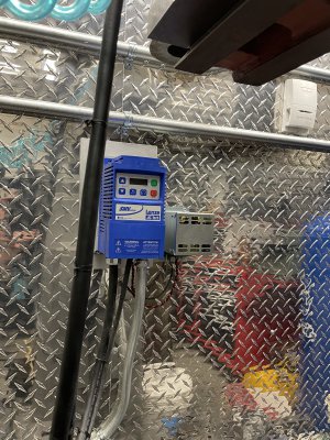
Dynamic braking module

akjeff

H-M Supporter - Gold Member
H-M Supporter Gold Member
Joined
Aug 21, 2020
Messages
692
Finally was able to get a dynamic braking module for the Lenze VFD that drives my 3hp Lagun mill. When using heavy cutters like face mills and fly cutters, or running tools at high RPM, the onboard braking of the VFD was no match, and it took forever for the mill to coast to a stop. Wire in the braking module, and wow, what a difference! Set the decel time to 1 second, put a heavy 4" face mill in the quill, and ran it at 1000 RPM. Hit stop, and it came to a halt in 1 second. Real happy with it. Then tried a reverse under power, and it worked like a champ. Going to have to experiment with power tapping now.
IMG_8303.JPG
 
It's nice when electrons do what you want them to
Get along little doggie electrons, get along :)
-M
 
Never knew there was such a thing, it works like a resistor but with more "dynamic" resistance?

Would love to see a schematic, something that could be homebrewed?

John
 
Never knew there was such a thing, it works like a resistor but with more "dynamic" resistance?

Would love to see a schematic, something that could be homebrewed?

John
Not only works like a resistor, it is a resistor! It's a series of several power resistors that take the place of the wimpy braking resistor in the VFD unit. There's a pair of conductors that feed the resistors, and then a four conductor control cable between the two. It's made by Lenze, who also make the VFD. Easy install, and worked first try. Just had to enable the "dynamic braking" option in the VFD.
 
It is just an external braking resistor, which has the ability to dissipate excess generated voltage vs. the internal resistor which is much more limited. They call them "dynamic braking resistors", dedicated ones for VFD's sometimes have a thermal sensor which can be wired to the VFD to shut it down if it gets too hot. This discussion comes up frequently, and the braking in lathes and mills is a very short time and then the brake is released, so they rarely get warm. In a hoist or high momentum system heat dissipation can be more of an issue.

Different VFD's deal with excess voltage generation differently, some it can lead to a VFD error and free run situation, others have programs to modulate the braking so one does not get into an over voltage scenario. The impact of an external braking resistor on stopping can be significant, but when setting the braking time it correlates to the stopping time from the maximum programmed speed, not the actual speed. Its sets the slope of the deceleration. I also usually set the slope to linear as opposed to S curve. I usually recommend something like a 2 second braking time, and for threading or tapping turn the VFD down to something like 20 Hz and it will stop/reverse on a dime.
 
Good VFD's can come with a connection pair to put a braking resistor, and @mksj is right, that without one, a VFD has to handle harsh voltage situations. When you power a motor, you are also turning a generator that is making a (high) voltage fighting back, and it is only the leftover difference between the "back emf" and the applied voltage that makes it go forward, the applied voltage being the winner. When power is off, but everything is still spinning, the rotational inertia of everything that is moving is turning a generator that raises the voltage bus, and it can be to the point of damage!

I found with servo drives that the resistor is usually a big fat one, mounted with a heat sink. Usually rated to be able to take about 10% to 20% of the full rated power, over a few seconds. Know that with full control, you have to pay attention to VFD parameters that set the maximum deceleration rate. It can slam to a stop so hard you can break things. More commonly, setting for a swift smooth stop can cause currents that temporarily exceed a trip limit. Again, the parameters normally allow a value, and a time it may be exceeded, and by how much.

A resistor is a simple addition, but what it gives you is just great - provided the VFD has that facility.
 
Last edited:
Good VFD's can come with a connection pair to put a braking resistor, and @mksj is right, that without one, a VFD has to handle harsh voltage situations. When you power a motor, you are also turning a generator that is making a (high) voltage fighting back, and it is only the leftover difference between the "back emf" and the applied voltage that makes it go forward, the applied voltage being the winner. When power is off, but everything is still spinning, the rotational inertia of everything that is moving is turning a generator that raises the voltage bus, and it can be to the point of damage!

I found with servo drives that the resistor is usually a big fat one, mounted with a heat sink. Usually rated to be able to take about 10% to 20% of the full rated power, over a few seconds. Know that with full control, you have to pay attention to VFD parameters that set the maximum deceleration rate. It can slam to a stop so hard you can break things. More commonly, setting for a swift smooth stop can cause currents that temporarily exceed a trip limit. Again, the parameters normally allow a value, and a time it may be exceeded, and by how much.

A resistor is a simple addition, but what it gives you is just great - provided the VFD has that facility.
I have come across some of these explainations but this one is very clear and helpful - thanks
 
Back
Top