- Joined
- Jan 12, 2019
- Messages
- 96
I began this post in a different forum, not realizing this Sheldon forum exists.
I got hold of an early Sheldon 10 Inch which is listed in a brochure as Model 1020. A relatively standards convention is that the 20 refers to the working capacity. As mine is 26 as opposed to 20, I am thinking the model is actually 1026. The serial number is L253 making its date of manufacture sometime in late 1933 or 1934.
When I got the lathe it had nine thread gears in addition to the gear that was installed on the lathe. The steady rest and follow rest were included, as was a face plate. The chuck is a three jaw universal but appears to be other than OEM.
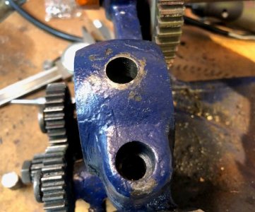
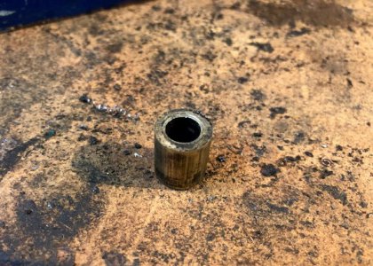
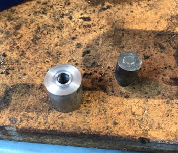
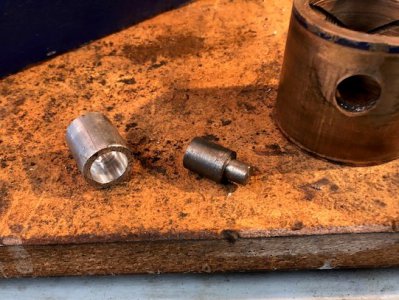
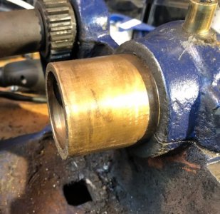
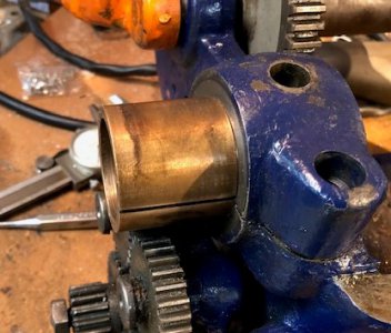
The cross-feed nut is somewhat galled out and should be replaced. The compound feed nut is in good condition with acceptable (for my needs) backlash. The near bushing on the head-stock needs replacement on an urgent basis. It appears to be a standard 1 3/4 inch bushing. I think I will find one without too much trouble.
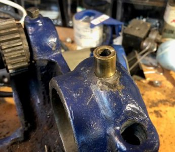
As of this moment, I am unable to move the main gear on the spindle. It does not appear that there is any locking mechanism that is holding the gear in place. I think it is just frozen. (I am trying to get the spindle out to replace the bushing. I am thinking the lathe comes apart like a South Bend 9 inch. Just remove the far end collar and push it out.)
The photos of this lathe are over on the antique machine forum. SO as not to use up a bunch of memory, I will leave them there until it becomes necessary to bring them here.
Any access to parts or advice on getting this gear to move laterally on the spindle would be much appreciated.
Tnx,
Doc
I got hold of an early Sheldon 10 Inch which is listed in a brochure as Model 1020. A relatively standards convention is that the 20 refers to the working capacity. As mine is 26 as opposed to 20, I am thinking the model is actually 1026. The serial number is L253 making its date of manufacture sometime in late 1933 or 1934.
When I got the lathe it had nine thread gears in addition to the gear that was installed on the lathe. The steady rest and follow rest were included, as was a face plate. The chuck is a three jaw universal but appears to be other than OEM.
The cross-feed nut is somewhat galled out and should be replaced. The compound feed nut is in good condition with acceptable (for my needs) backlash. The near bushing on the head-stock needs replacement on an urgent basis. It appears to be a standard 1 3/4 inch bushing. I think I will find one without too much trouble.
As of this moment, I am unable to move the main gear on the spindle. It does not appear that there is any locking mechanism that is holding the gear in place. I think it is just frozen. (I am trying to get the spindle out to replace the bushing. I am thinking the lathe comes apart like a South Bend 9 inch. Just remove the far end collar and push it out.)
The photos of this lathe are over on the antique machine forum. SO as not to use up a bunch of memory, I will leave them there until it becomes necessary to bring them here.
Any access to parts or advice on getting this gear to move laterally on the spindle would be much appreciated.
Tnx,
Doc