

-
Welcome back Guest! Did you know you can mentor other members here at H-M? If not, please check out our Relaunch of Hobby Machinist Mentoring Program!
You are using an out of date browser. It may not display this or other websites correctly.
You should upgrade or use an alternative browser.
You should upgrade or use an alternative browser.
Easy indexable, tool free, self locking lathe insert holder.
- Thread starter Parlo
- Start date
- Joined
- Feb 21, 2022
- Messages
- 772
This model was made to face up to 50mm diameter. It could be slightly tilted to clear any diameter face. I need to see how to set a tilted insert on the centre and how it behaves.Interesting.
No sharp inside corners.
What depth of cut can you get?
Can it face too?
Thanks,
Brian
I believe that the manufacturers maximum depth of cut is the insert radius, although I have milled Delrin at 12mm deep with a 20mm diameter button insert - without chipping on exit.
- Joined
- Oct 11, 2016
- Messages
- 3,868
I really like your idea!
Can you do a follow up with more detail? I've never seen a button insert quite like that before, for instance. What is the relief angle of the insert? What is the rake angle? What brand?
The base seems to handle the locking function: is is just friction? Or do you have mating crown gear-like structures under the flange?
So many questions! In order to "stand on the shoulders of giants" we first have to fully understand their accomplishments.
Congrats on a very nicely made tool,and great concept!
- Joined
- Aug 13, 2020
- Messages
- 1,342
Could you just leave the screw loose on one of the standard tools?
 www.ctctools.biz
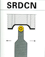
SRDCN INDEXABLE TURNING TOOL HOLDER #I32
indexable iso standard lathe turning tool holder with screw clamping for Carbide Insert
- Joined
- Feb 21, 2022
- Messages
- 772
I'm sure the screw would loosen or tighten depending on the direction of the cut, there would be no concentricity or stability. The whole spindle revolves in oilite bushes with the insert located in a shallow pocket & the screw tight.Could you just leave the screw loose on one of the standard tools?
SRDCN INDEXABLE TURNING TOOL HOLDER #I32
indexable iso standard lathe turning tool holder with screw clamping for Carbide Insert
- Joined
- Feb 21, 2022
- Messages
- 772
I will post an image of the parts and insert detail. It gives a brilliant finish on Aluminium although my filming does not do it justice.I really like your idea!
Can you do a follow up with more detail? I've never seen a button insert quite like that before, for instance. What is the relief angle of the insert? What is the rake angle? What brand?
The base seems to handle the locking function: is is just friction? Or do you have mating crown gear-like structures under the flange?
So many questions! In order to "stand on the shoulders of giants" we first have to fully understand their accomplishments.
Congrats on a very nicely made tool,and great concept!
Tool image + insert details here - https://drive.google.com/file/d/1sYSWkMB8KtpropK3spa7OvSeeA5WFuiQ/view?usp=share_link
The insert spindle rotates freely until a tangential load is applied when friction locks it. If.. it did happen to rotate when cutting I'm sure that would not have a detremental effect.
If I could refine the geometry to make the insert roll along the surface it will have the benefit of constant even wear around the perimeter of the insert. This would allow for greater cutting time between insert changes. Using the whole perimeter instead of using the 6 or 8 locating flats on the bottom of the insert would also extend the inserts life. If the tool is always fed towards the chuck and towards the centre I suggest turning the insert when dull, slightly anticlockwise to expose the fresh part of the edge nearest the part surface.
Another benefit of having the insert "rolling" along the part surface could be deliberately making the insert eccentric to the spindle which would smoothly vary the chip thickness & possibly breaking stringy chips.
Lots of development to do, perhaps anyone interested could sugest other improvements and conduct their own trials.
Last edited:
- Joined
- Jul 29, 2014
- Messages
- 2,737
Perhaps the post for the insert is not needed...just extend the shank of the holder and set the insert on the shank with the working edge exposed adequately. Would improve rigidity and simplicity, I would think.
- Joined
- Feb 21, 2022
- Messages
- 772
Good thought. The heads of the oilite bushes I had available yesterday were greater than the diameter of the insert so I popped it on an extended spigot for clearance when facing the ends. It would work as you say if the spigot assembly and support were all smaller in diameter than the insert.Perhaps the post for the insert is not needed...just extend the shank of the holder and set the insert on the shank with the working edge exposed adequately. Would improve rigidity and simplicity, I would think.
Thanks for the idea, my next step will be to investigate setting the insert at a compound angle to give the required clearances, allowing a simpler and lower spigot to be used.
- Joined
- Oct 11, 2016
- Messages
- 3,868
Instead of a parallel post with a flange to hold the insert, You might consider a conical or even a conical curve. I'm a big believer in minimizing the stress risers and making the lines of force smoother.ots of development to do, perhaps anyone interested could sugest other improvements and conduct their own trials.