Edison 1340GH

ljamester

Registered
Registered
Joined
Jun 28, 2021
Messages
8
Hi
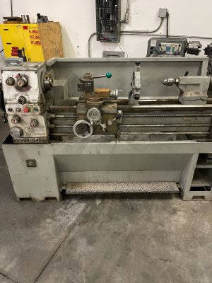
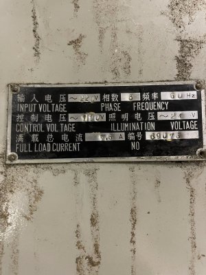
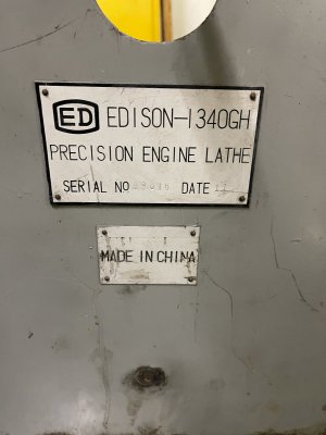
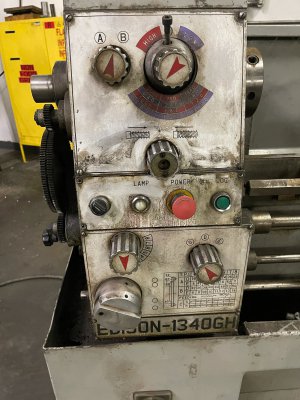
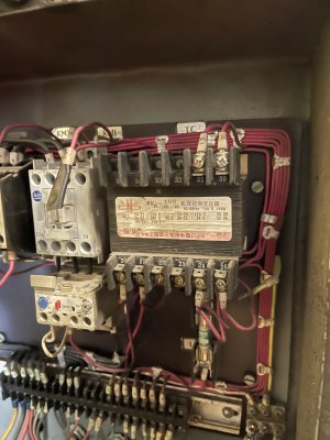
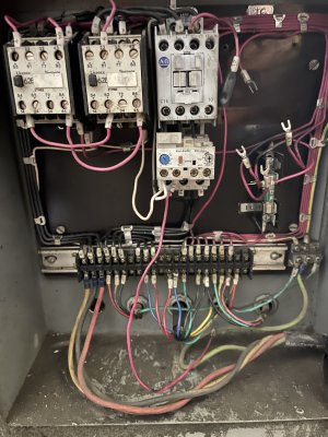
Im looking for information on an Edison 1340gh lathe. specifically electrical information. If anybody has an owners manual with a wire diagram that would be awesome! or even just a picture of the electrical panel in the back of the lathe.
From what i understand this lathe was manufactured by DAR SIN and they sold the lathe under several different names. (DSL 1340gh) I recently aquired this lathe and would love to work past the electircial issues and get it running.
thank you
 

Attachments

  • image0.jpeg
    image0.jpeg
    1.9 MB · Views: 311
  • image2.jpeg
    image2.jpeg
    2.1 MB · Views: 208
  • image3.jpeg
    image3.jpeg
    1.8 MB · Views: 197
  • image4.jpeg
    image4.jpeg
    2.1 MB · Views: 245
Your lathe requires 3-phase power so if you don't already have a 3-phase supply you'll need either:
A) a static phase converter- cheapest, gives 2/3 motor power, simplest
B) rotary phase converter- costs more, requires no modification to lathe electricals, can run more than one machine at a time
C) variable frequency drive or vfd- moderate cost, requires bypassing motor contactors and some other wiring work

The 4th option would be to change out the motor for a single phase one, but 3-phase motors tend to run a bit smoother and are more efficient

Check motor nameplate for horsepower rating if there is one- I'm guessing about 1.5 HP?
-Mark
 
@ljamester ,
i would gladly share the manual i have, but unfortunately, it is for a smaller lathe, and by the looks a different control panel. sorry.
i can say, that your system is 24v, by the nametag.
it will have reversing contactors, interlocked to prevent energizing both contactors at the same instant
it will have a transformer to step line voltage down to 24v, for control purposes.
this 24volts is used to go through your control switches and to pull in the contactors and relays present in the control system

if you can explain the nature of the problem you are experiencing, i may be of some assistance in troubleshooting
 
Your lathe requires 3-phase power so if you don't already have a 3-phase supply you'll need either:
A) a static phase converter- cheapest, gives 2/3 motor power, simplest
B) rotary phase converter- costs more, requires no modification to lathe electricals, can run more than one machine at a time
C) variable frequency drive or vfd- moderate cost, requires bypassing motor contactors and some other wiring work

The 4th option would be to change out the motor for a single phase one, but 3-phase motors tend to run a bit smoother and are more efficient

Check motor nameplate for horsepower rating if there is one- I'm guessing about 1.5 HP?
-Mark
I have all the power requirements. i aquired the lathe from a larger company that was getting rid of the lathe.
the transformer on the lathe was blown. im not sure if sombody had messed in the back and replaced a contactor or something and wired it incorectly. the transformer is 220 primary 110 and 24v secondary befor i replace the transformer i wanted to verify it was wired corectly but i cant locate a manual or a wire schematic.
 

Attachments

  • IMG_9761.jpg
    IMG_9761.jpg
    1.6 MB · Views: 221
the overload contactor at the base of KM1 is tripped
the little gray button that resembles a phillips head impression, is pushed out
push the phillips shaped button in and twist it clockwise until the arrow head points straight up
this will allow the control system to function for troubleshooting
 
the overload contactor at the base of KM1 is tripped
the little gray button that resembles a phillips head impression, is pushed out
push the phillips shaped button in and twist it clockwise until the arrow head points straight up
this will allow the control system to function for troubleshooting
Here is a better view of the control power panel.
 

Attachments

  • IMG_9804.jpg
    IMG_9804.jpg
    2 MB · Views: 217
is Y and 12 connected under the tape????
if so, they may have put the wrong voltage contactor coil in this machine
to elaborate, a 24v contactor is necessary, if the hack that worked on it before installed a 115v coil contactor in, well it wouldn't work as intended
i would verify this before proceeding any further
they are not connected. 12 was not connected to anything.
I was also thinking that somone installed the wrong contactor.
 
whew, an optical illusion!
i would verify the coil voltage at least
 
Back
Top