Embark into the unknown

Jubil

H-M Supporter - Sustaining Member
H-M Platinum Supporter
Joined
Apr 13, 2016
Messages
336
As the title suggests, I am about to embark on a project. And I am unsure if I can (with my limited experience) achieve the needed accuracy.
So, if you guys don't mind helping me out I would greatly appreciate it.
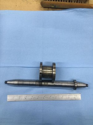
The photo shows a spindle shaft from a Brown & Sharpe #13 universal grinder, around 1942 vintage. I hope to make another shaft that is about 1" longer, adding the extra outboard of the disc. I want to add a v-belt or poly rib pulley to that end so that I can run the spindle from a separate 2 hp 3 ph motor instead of the flat belt that it originally had. The original pulley is shown in pic also. The reason for changing is the flat belt flips over and cost $$$. From what I can tell the motor is too old and incompatible with a vfd that I would like to add also.
There are 3 things I would like to ask;
What would be the best pulley & belt size & style? (Max rpm around 3500 with 1750 rpm motor. Up to 8" wheels)
What suggested order of operations?
Best method of attaching the disc at the right end? Press fit, shrink fit, braze or solder? This disc acts as a end play stop.
The old shaft measures 0.996 in the unworn areas.
The new shaft is 1 inch diameter 1045 polished & ground and I plan to use hss tools. I have insert tools but I have more trouble with accuracy.
I also plan to keep the old parts to be able to return to original if the need arises.
Thanks in advance for your help
Chuck
 

Attachments

  • thumbnail.jpeg
    thumbnail.jpeg
    93.9 KB · Views: 35
Your not going to make an accurate spindle on a lathe no matter how good the lathe is. It needs to be ground.
 
Concerning belt design and configuration
Why not stick to the common V belts? Easy to find A size V belts and pulleys My delta wood joiner is has a 1 hp 3600rpm motor and a V belt speed increase to somewhere in the 5k rpm region.

Rubber V belts and V ribbed belts are limited to 30 m/s at tangent to pulley.
According to page 275 of the book Machine Design Fundamentals by Zimme Hindhede


8in Dia max pully = 203.2mm = 0.2032m

Pi*0.2032m = 0.63837m perimeter

0.63837m *1725 r/60s= 18.353m/s at tangent.
No issue running a V belt
For power rating 2 horsepower is well with in the range of an A Belt (See top of Page 7)
 
Luckily the parts manual is freely available for all to view. This is part 1 of the machine, and with that much wear of the shaft you will need to replace it anyway. Page 6

The closest thing I made to this was some shafting for an articulated arm to be placed in a vacuum chamber at McGill University. My mentor made the forearm and humerus on the VMC while I made the mounting bracket and shafts manually. All ABEC 7 bearings as to minimize the play at the end of the arm, all tolerances were correspondingly small. I had a Hardinge Toolroom lathe at my disposal. 1.125" shafting was used 25mm bearing bore Dia and 18mm threads and the sort all a foot long or shorter. The sections where the bearing seat were 10um-15um window tolerance for press fit. Double that on length to shoulder. Using multiple test cuts, and having one micron micrometers, two micron test indicators over on the granite. and a one micron DRO were essential. Carbide insert tooling was used, calibrating after each tool change. approximately equal depth of cut on test and to finish cut to get tool pressure predictable.
Suffice to say that this part can be made one a lathe. In a production setting or when dealing with a hardened shafting, Then you need to grind such a part. Dress once, test cut a few times, then you can run a batch and only to repeat when the successive parts start to slip off tolerance.

For this part in particular, I would have to see how this comes together to judge tolerances.

As a bench mark for the kind of end results we want the book Testing Machine Tools by Georg Schlesinger, says to have 5 um of total indicated run out radial and 10um axially. Effectively 2 tenths and 4 tenths of a thou. Not a small task to achieve, I'm more concerned as to the needs of the bushings that are interfacing, the wheel spindle box left and right. Parts 2 and 3. where do the mating surfaces pinch the shaft limiting axial movement? What adjustments do you have? where do the bearings split for them to be scraped? Or are they one piece? hard lapped or non ferrous metal?

Thanks Alexander for the prompt reply.
First of all; real accuracy is probably not attainable by me or my Grizzly lathe. This project will be a challenge for sure, and a learning experience I hope. But I would like to give this a good shot. I don't expect to do tool room work, just sharpen tools and minor surface grinding. I don't have any of the accessories or peripherals just the basic machine and some homemade jigs for sharpening different items.
I don't know what the original shaft diameter was I just measured where it didn't seem to be worn. But the new 1" shafting will not fit into bearings. I haven't measured id of bearings yet.
The bearings are solid brass except for the holes that you can see in the diagram, and a slot for the oiling felt. There are spring loaded plungers that go in the holes that I assume apply axial load. End play is adjusted with a split nut that is captured under the flat belt pulley. I don't even plan to install new bearings at this time.
Thanks again
Chuck
 
Concerning belt design and configuration
Why not stick to the common V belts? Easy to find A size V belts and pulleys My delta wood joiner is has a 1 hp 3600rpm motor and a V belt speed increase to somewhere in the 5k rpm region.

Rubber V belts and V ribbed belts are limited to 30 m/s at tangent to pulley.
According to page 275 of the book Machine Design Fundamentals by Zimme Hindhede


8in Dia max pully = 203.2mm = 0.2032m

Pi*0.2032m = 0.63837m perimeter

0.63837m *1725 r/60s= 18.353m/s at tangent.
No issue running a V belt
For power rating 2 horsepower is well with in the range of an A Belt (See top of Page 7)


Thanks, this is just the information I was looking for.
Chuck
 
Back
Top