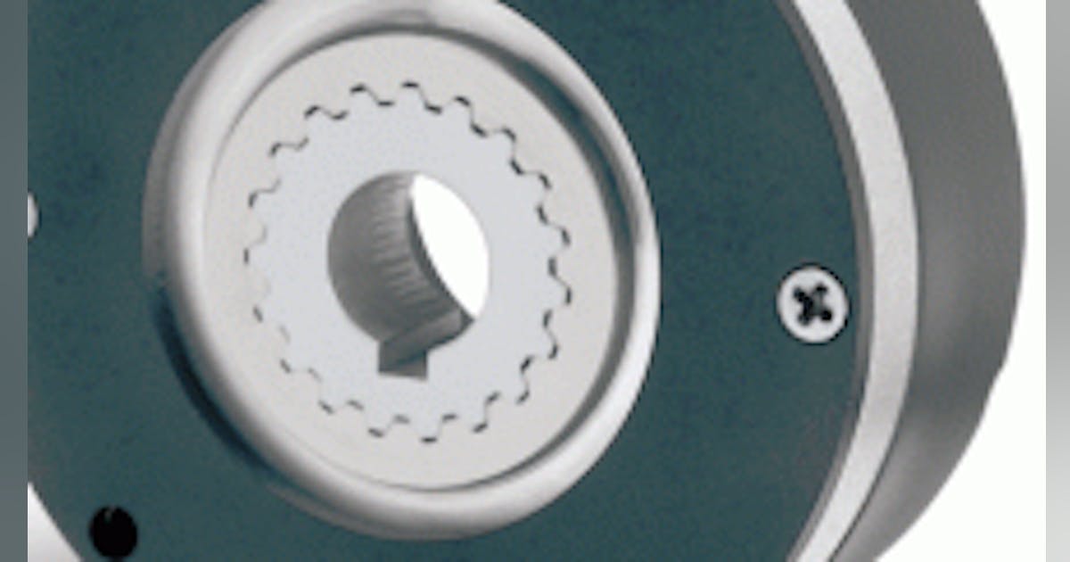
EMCO V13 - Brake Lock-up Problem?

Here's the high-tech brake release. It works fine but you don't get instant response from the power supply because there are big capacitors in there. I may rig up a momentary switch to apply the brake manually (and instantly). In any case, this will allow me to finish the job I was working on when the problem happened and use the lathe for other tasks until the new rectifiers are delivered.
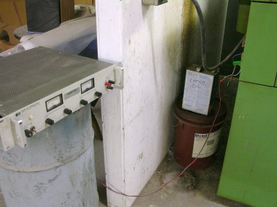
Temp Brake Release.JPG
 
I'm back in business.

The rectifiers from DigiKey showed up today (not only the cheaper source but the best service!) and the lathe is now working again just as it has for the previous 38 years. One advantage of the DigiKey-sourced part other than the layout of the tails is that there's a mounting hole in the center of the part. The original rectifier and the terminal strip were bonded to the inside of the cover with some unknown adhesive that did its job perfectly for all these years but I wasn't sure what to use in its place. I could use 3M 2216 or maybe RTV but what ever I use will be paired with a nylon 6-32 screw tapped into the cover and maybe heat-staked from the outside just to make sure it stays put.

Again, many thanks to mksj for all the help with this problem. I expect this will not become an issue again in my lifetime.......Bill

 
Last edited:
Glad it worked out for you, and agree the new replacement should last a long time. I would just mount it with any adhesive and you can use a metal screw, no need for nylon. The main reason to secure it in this application would be to prevent lead breakage from vibration over time, in other settings the rectifier specifications at 20A is dependent on using a heat sink to dissipate the heat. One reason why the original rectifier may have failed is that when the brake releases, it cause a reverse voltage spike that can be quite high. This is one reason why relays and contactors often use some form of snubber or reverse diode depending on the application. With a simple 24VDC relay I measured these voltage spikes in the 160V range, and I would imagine with elector-magnetic brake/clutch the spikes could be quite a bit higher back to the diode bridge. A simple solution is to put a small capacitor or RC snubber across the DC leads. This came up recently in another forum and what was used was a ~0.27uF 600-1000VDC film capacitor, but different options. Given the size and voltage of the rectifier it probably will not be an issue but FYI.
 
Back
Top