Emergency brake

Torbo

Active User
Registered
Joined
Feb 2, 2014
Messages
112
I´m planning to make a emergency brake to my Crusader lathe.
I'm thinking of making an iron rod hinged at each end, with a electrical switch connected in series with the stop switch.

Has anyone made ​​such and can anyone give me some ideas about this project?
 
I´m planning to make a emergency brake to my Crusader lathe.
I'm thinking of making an iron rod hinged at each end, with a electrical switch connected in series with the stop switch.

Has anyone made ​​such and can anyone give me some ideas about this project?

Maybe a string can do the same thing as an iron rod?
 
I assume you want to install this as a foot operated switch. This is a common way to do it, many lathes come factory equipped with this system. Normally it also operates a mechanical spindle brake. Connecting the new switch in series with the stop switch is the correct way to do it. I don't really have any advice on the best way to build it, but it needs to be designed so that it will not fail in use. There are cable operated safety switches available. Here is an example of what I am talking about: http://www.automationdirect.com/adc...ax_Protection_Length_(SDM2_Series)/SDM2K96X11
 
Thanks! Maybe a string can do the same thing as an iron rod? Then I can have two, one in knee height and one in shoulder or abdominal height?

I will try that to morrow
 
Thanks! Maybe a string can do the same thing as an iron rod? Then I can have two, one in knee height and one in shoulder or abdominal height?

I will try that to morrow


Yes, I think so. Exactly how you make it is not so important, that it works when you need it is the most important.
 
I think emergency stop is a better name than brake. Im thinking of a electrical engine brake, but that is not possible with at AC-motor I have heard. DC motors is easy to stop, only to put the + to ground after switching off.

To day I will make a string arrangement for cutting the electrical wire/switch for the engine.
 
You can electrically brake an induction motor by applying DC to one of the windings. It does require some calculations to determine the voltage and some relays. The DC must be disconnected quickly when the motor stops. It won't hold the motor: just slow it quickly.
 
Thanks! That was interesting! Do you have some drawings? Shema?
I was thinking of to put in some rectifiers/diodes in a loop in the stop phase?

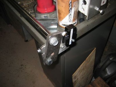
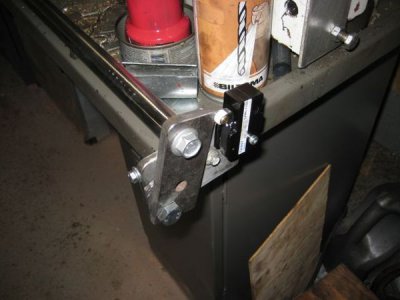
In the first time I will have this mechanical electric stop:

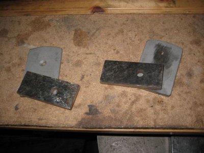
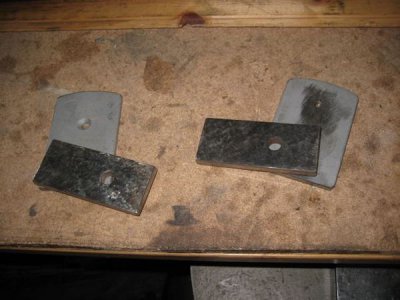
Five flat iron bits and a little extra. The iron rod was 20 mmm i diameter.
It worked well
Fire flatjern men det kom et lite stykke til for å tilpasse bryteren.
25fssxh.jpg
In the end I used a micro switch
1y0p42.jpg


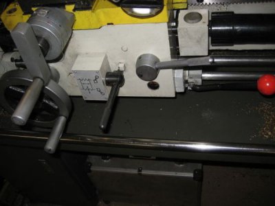
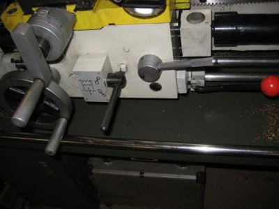
It is to little plase for the start stop hen del, but I will fix that tomorrow
343opbt.jpg

25fssxh.jpg

1y0p42.jpg

343opbt.jpg
 
FWIW: I added FWD, REV and JOG to my milling machine using a few relays. But I also wanted it to spin down much quicker, so I added a dead short across the normally closed contacts of the power relay. This shorts across the the motor's L1-L2 windings when the relay drops out. It seems there is just enough remaining magnetic field in the motor when this relay shorts that it brakes the motor to about 50-60% of it's operating RPM VERY quickly, at which point the field collapses and it coasts to a normal stop.

The comment about adding brief DC to a winding got me thinking; maybe I can replace the short with an appropriate sized capacitor/resistor combination that is charged while the motor is running. Hmmm...

Mark
 
Forgot where I read about someone used a motorcycle disk hydraulic brake, master cylinder with a wide brake pedal. The brake pedal has a plain ole stop light sw. The switch then
went to a relay that interupted the power feed (before the drum switch) I thought that was slick. If I remember correctly this was an under drive S Bend so all was hidden in the
cabinet. I think the brake rotor was attached to motor drive pulley?? but it kills power and stopped it on a dime.....
 
Back
Top