Enco 110-2033 lathe electrical issue

Nailzscott

Registered
Registered
Joined
Mar 22, 2022
Messages
10
I have her this Enco lathe that I bought from a school that has a bad power transformer. Has anyone ever replaced one of these and, if so, do you have a resource that won’t cost me a small fortune? I’ve found some that might work but are too big to fit where this one does.

Thanks
 

Attachments

  • 5D930A00-5DD8-489E-B6DE-16A4B9F40D7A.jpeg
    5D930A00-5DD8-489E-B6DE-16A4B9F40D7A.jpeg
    88.3 KB · Views: 13
Have you checked the transformer, you can remove the connected wires and check the ohms between the terminals, output should be about 1/2 of the input.

All you need to do is match up a transformer with the same/similar ratings, the transformer should just be required to operate the contactors which doesn't take much current. Can't read the name plate but looks like a 50 or 60VA, so you would want what is called a control transformer with an input of 220, 230 or 240VAC and an output of 110, 115 or 120VAC that matches the size of what you have. Many of these can be configured for dual voltage input like 22/440 if coils are connected in series or parallel. Some examples below.
 
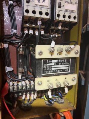
mksj: thanks for the input. The nameplate on mine is a 50VA and I've been looking at them. Ebay has a lot of options but the ones I've looked at do not have dimensions - and that's important due to the space in the box.

I want to make sure I understand the wiring on the new ones. My current transformer has 2 110v wires coming into the primary (top) terminals - when it was working.

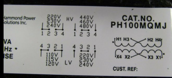
On the nameplate of the New Hammon, do I understand it correctly to mean this:
On the primary (top) side where the nameplate says 220v, 230v, 240, connect one of the top terminal wires from the old transformer (which is 110v) to terminal 1, and the other top 110v wire to terminal 4, bridging 1 & 2 and 3 & 4. Then on the bottom secondary side, connect the 2 wires that are on the bottom side of the old transformer to the terminals 4 & 1 - with 4&3 bridged and 2&1 bridged.

I just want to be sure I'm interpreting it properly.

Thanks
 

Attachments

  • Relay pic.jpg
    Relay pic.jpg
    46.5 KB · Views: 6
I would take a meter and check the output voltage before deciding it was bad. Normally if a transformer goes out you can see burnt windings and smell it. Make sure that's the problem before replacing it.
 
On the question "is it bad", I had a bad relay (where the contacts were fused together) and I replaced it with a new one. I fired up the lathe and it initially fired up correctly, but when I put it in reverse, the new relay struggled to engage. I tested across the secondary terminals and found that power was intermittent - even causing the lathe's power light the flicker off and on. I touched one of the secondary terminals with my meter probe and the power light flickered. So today I will check the power transformer's voltage and look for anything loose on the terminals. I will also do a resistance test as suggested by mksj.

I'll let you know.

Thanks
 
I just checked the transformer out again and found a broken wire on the back side of one of the connection posts. It still had enough wire so I reconnected it and tested ohms - and found no resistance. So it's dead and I'll need to find a new one.

If someone can confirm my earlier post (with the picture) regarding properly connecting a new transformer with that name plate detail - I'd appreciate it.
 
You can look up the transformer part number to get the dimensions to see if it will fit, I think the critical dimension will be the height, the base dimensions look to be a bit smaller than what you have. The machine should be 220-240VAC input power, the control transformers are usually used to reduce the voltage to 110-120VAC in your application. The connections are usually specific to the input voltage, so just follow the connection terminal diagram for the transformer you choose. The 220-240VAC the lower input windings are in parallel, 440-480VAC higher voltage windings are in series. In the transformer below you connect a jumper from 4 and 2, a jumper from 1 and 3; power in to terminals 1 and 4. The fuse holder can be removed if the output line is already fused.

Height 4 in
Length 3.46 in
Width 3.38 in


TB100A008C.jpg
 
Ok. The base on my old one is really close to the dimensions you referenced; except it's not quite 4" tall - but should fit.

My supplied power is 240, so the two 120v lines feed the primary of the transformer, which on your picture diagram will be the top left - terminals 1 & 4 with 2 & 4 jumped and 1 & 3 jumped - as you stated. The lower part of the diagram on the picture shows where I connect my 2 lines that feed 120 to the control relays.

My current transformer is 50VA vs the 100VA on the one pictured. Is that an issue to go to the higher one?

Thanks again.
 
Not an issue going with a 100VA, if the output (120V) is not fused, I would use the fuse holder with a 1A fuse.
 
Back
Top