Enco 111-3100 lathe

70sum

Registered
Registered
Joined
Apr 13, 2023
Messages
15
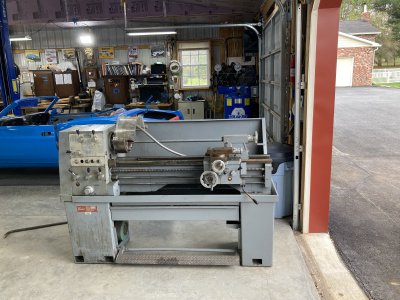
I just purchased a used Enco 111-3100 lathe. I am trying to run it with a VFD. No luck so far. Is an electrical schematic available any where?
I had to replace some of the switches that were broken. Stop button, jog button and oil pump button. Was hoping to find a schematic to double check the wiring.
thanks in advance for any info.
 

Attachments

  • DHGK0971.JPG
    DHGK0971.JPG
    623.3 KB · Views: 34
Hey Captain ! Mark will be along soon . :)
 
Welcome aboard Bruce . :encourage: We have some great guys on here when it comes to this SES ! ( secret electrical S**t )

They'll walk you thru it in a jiffy . And , the truck is done . :)
 
Welcome aboard Bruce!
It was great meeting you and not seeing your lathe tip over while moving it!
Looking forward to seeing you fire that thing up! It will look great in you're awesome shop!
:welcome:
 
hmmm....
You're positive that's the model number? It does look like a good Enco # but no luck on a manual/diagram...

Appears to be a Sharp 1340E clone? (or another clone of whatever the Sharp 1340E is a clone of?)
1681478294270.png

 
You are aware that the output of the VFD must connect directly to the motor? The lathe buttons should be wired to the VFD not the contactors/power
and the VFD programmed accordingly
Changing the button wiring to the VFD control inputs can be considered a separate project- in the beginning it's easiest to run the VFD locally off it's own control panel
 
Last edited:
Mark
It makes sense to me to hook up to the motor leads direct. That is what I was going to try to see if the motor is good. Since I do not intend to run the coolant pump I would not need to worry about wiring that. This is the first lathe I have seen in my 50 years as a machinist that has a jog button. Do not know if I need that either. Do not know if the pilot light is needed either. The motor start switch and stop button are really what I think I would need.
I also purchased a milling machine and was hoping to be able to run that from the VFD. I planned to have 220 plugs on the wires so I can switch to the machine I need to run. Was planing to just unplug and switch to the other machine as needed. Trying to save from buying another VFD or rotary converter, since I will only be running one machine at a time.
I have not tried the mill yet. Would it have to rewired or can I just put the male plug on the cord that is already there? I have not opened up any junction boxes yet, but it would seem to me that I should be able connect to the gn,w,v,and u and plug into the female plug I have to hook to the
gn,w,v and u terminals in the VFD.
Sorry for the rambling, just thinking out load.
thanks for the info
I am sure I will be back for more.
 
Sounds good- only thing I would mention is that switching the VFD between two motors you may find that you need to change a couple settings
to get optimum performance if the motors look sufficiently different to the VFD, electrically speaking. They may have similar or even identical
nameplate specs but may have different inductance, resistance, etc. and VFDs are sensitive to that. They "tune" themselves to the motor.
You also want to be sure that the motor does not become disconnected under power as that can damage the VFD output stage.
-M
ps Multiple motor setups (or one machine with multiple motors) are a good case for RPCs (rotary phase converters) for those reasons
 
Last edited:
Mark
I hooked the VFD directly to the motor and the lathe now runs. Thanks for that info.
Now on to the milling machine. Think I will just purchase another VFD.
I still need more education on VFD's. I will be back with more questions.
 
Back
Top