- Joined
- Nov 23, 2014
- Messages
- 2,606
Back with yet another reproduction Erector set part. This one is part number “IA”, Zeppelin swivel assembly. I’ll start with the obligatory history lesson. . .
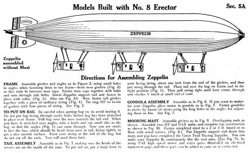
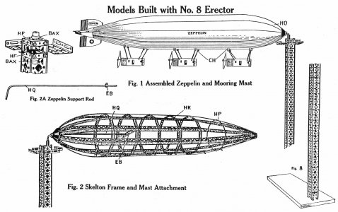
Germany’s Graf Zeppelin went on a round-the-world tour in 1929. The nearly 800’ long rigid airship was received with much awe during this tour. The A. C. Gilbert Company capitalized on the fervor by introducing an Erector set in 1929 that built a 5’ model of the Zeppelin. And “NO”, Gilbert did not include a canister of hydrogen to inflate their model! Here are a few manual pages showing the model.
Manual pages showing the construction of the 5' Zeppelin model. The Erector girder superstructure was covered with a cloth bag.
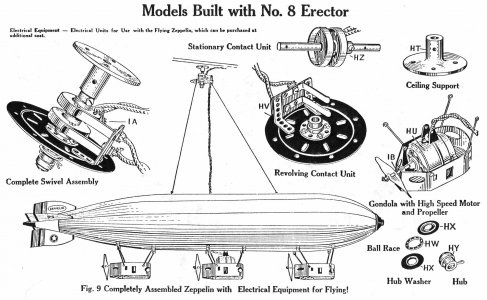
Here's the drawing of the "IA" swivel assembly and the components.
And a couple of photos of my reproduction
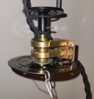
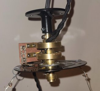
Gilbert offered an “only available from the factory” part number “IA” swivel assembly that hung the model from the ceiling and through a couple of contact drums brought 110V down to a motor in one of the gondolas to spin a propellor. This was a static display as the propellor/110V motor didn’t generate nearly enough wind to move the model. I suspect it was more for a store display. By the way, the “IA” swivel unit cost $2.50 from the factory back in 1929. I have seen TWO original swivel units in 25 years of collecting Erector sets; one in a collection, the other on eBay. I’ve had this one on my “to do” list for quite a few years and finally put in the time to make a few.
Projected volume influences the way I make these parts. CNC is nice, but if the volume in really low, it makes more sense to make up the components manually. I plan on making less than a dozen of them for a first run. If the volume warrants it, I’ll end up retooling some of the components that I currently do manually.
Gilbert was a master of repurposing existing parts to new applications. The part that I most struggled with was the “HZ” contact drums. These were made from brass and were secured to a central 5/16” rod with a brass hub. The hub was peened to a fiber disk which in turn was riveted to the “HZ” drum. The hub is identical to the bushing/plate riveted to the bottom support plate which is common Erector set part number “BA”. The fiber disk was 1 ¼” diameter which is also common with another Erector set part with a smaller hub that I make. Bonus! I got to share some tooling!
I tried making the drums by metal spinning but failed. Then tried to manually peen the brass disk over a mandrel heating it frequently to anneal the brass. Another failure. Third attempt was with a draw die that my father-in-law had for a similar steel part used on a toy wagon. The blanks kept splitting so I went with plan “D”: solder a disk inside of a piece of tubing. The drums are 1 ½” diameter with a 0.300” face and a bottom with a ¾” hole at the center. I bought some 0.040” thick seamless 1 ½” OD brass tubing off Amazon, chucked it up in the lathe and parted off 0.300” rings.
For the bottom plate, I used some 0.040” brass stock. These needed to be cut into disks with an OD of around 1.415” with a ¾” center hole. I thought about using carpet tape to secure the brass to an aluminum plate and drill/cut them on the CNC, but ended up with a very manual process. I’ll end up making around 24 of these, so the CNC route is looking good if I make more. I cut 1 ½” squares of brass, punched a ¾” hole, stacked them on a mandrel and turned the OD on the lathe. The drum bottoms have 4 holes on 1” centers at “12, 3, 6 and 9 o’clock” that are riveted to the fiber disk. For this, I turned a chunk of plastic with a bored 1 ½” ID hole. This piece went to the Bridgeport, found center with a Blake co-ax, and drilled holes for transfer punching the hole locations to the brass bottom.
Turned a double-ended mandrel with 1/2" and 3/4" shoulders and a 5/16"-18 center hole. My plan was to stack punched blanks on the mandrel, slip a clamping sleeve over the mandrel and bolt it down. Then turn to diameter on the lathe.
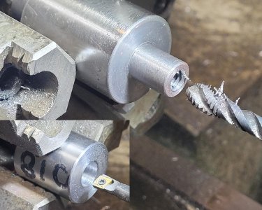
Here's a couple of brass blanks stacked on the 3/4" end of the mandrel. The OD of the brass is turned so around 1.415"; if I was making a pile of them I'd make a punch and die. But for a handful. . . The fiber material is turned down to 1.25" diameter; I found a punch/die this size so ended up not using the 1/2" end of the mandrel.
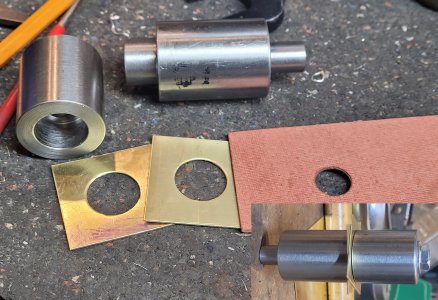
Brass tubing up top (parted off on the lathe) and turning some brass blanks to diameter.
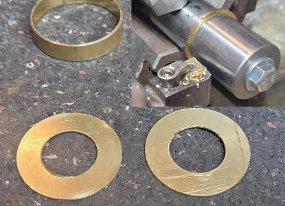
Didn't show a lot of the ops here. Bored a piece of plastic to 1.5", found center on the Bridgeport with a Blake Co-ax, and drilled holes for transfer punching locations to the brass and fiber disks.
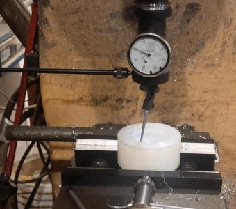
Then turned a second plastic piece to 1 ½” OD so the two plastic pieces nested together. The smaller piece has a shallow ¾” shoulder to center the brass disk for transfer punching. I did those holes with a RW No. 5 hand punch. After that, Scotchbrite’d the brass clean, applied a little flux and soldered them together.
Picture of the drums after punching the mounting holes in the brass bottom and fiber board. I didn't show it, but turned hubs from 5/8" brass with a 5/16" center hole for the main axle. Set the brass disk inside the brass drum and soldered in place. Used a steel ball and ball peen hammer to peen over the edge of the brass hubs to the fiber disks. Then used tubular rivets to attach the fiber disk to the drum. The fiber disk electrically isolates the hub from the brass drum.
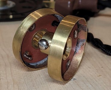
The fiber disk has a center hole ½” diameter, OD is 1.25”. I have an unhardened punch & die I use for a similar Erector set part; no new tooling needed here! Knocked out the disks, punched the ½” center hole, and used a similar 1 ½” OD plastic piece with a ½” shoulder to center the disk in the transfer punch fixture.
Four hubs are used in each full assembly. The hubs are made from 5/8” diameter brass with shoulders on either end turned to ½” diameter. Three of these get an 8-32 tapped hole, while a fourth one gets a through-hole drilled for a cotter pin (and becomes part number “HY” hub). I made a drill bushing from 1” O-1 to do the 8-32 tap hole. The shoulder on the brass hub is ½” diameter with a 0.300” face. The tap hole is centered on the 0.300” face. Did the work there on the Bridgeport with a square collet. Tap drilling and tapping was done on the lathe with cordless drills. The three hubs that get peened to brass or steel disks get a countersink on the back side to facilitate peening. Peening was done with a holding fixture, a big steel ball, and a 2 lb. ball peen hammer. The steel disk used in the bottom “BA” part came from recycled existing Erector set part number “BT”. Chucked those on the lathe, and used a countersink to remove the peened hub. The disks have a 9/32” hole which was opened to ½”. These were drilled out on the lathe using a 5-C emergency collet to grip the OD. Sorry, didn't have pictures of any of this.
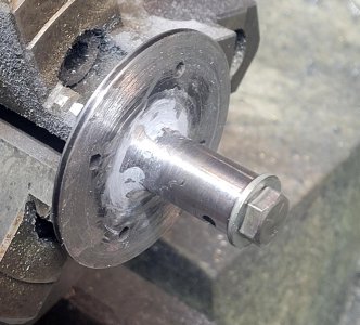
Next was the “HT” ceiling support. I made these from 1/8” steel plate and a 5/8” diameter steel round which were welded together to make a part that resembles a pipe flange. I used the Tormach to make the 1/8” round plate and drill the ceiling mounting holes. The 5/8” steel rod was drilled out on the lathe for the 5/16” axle rod, and a 1/8” long shoulder at ½” diameter turned for nesting into the disk. Then over to the BP to drill a cross-hole for a cotter pin. Couple of hits with the Hobart MIG welder, then add a fillet of JB Weld, clean up the fillet on the lathe and paint.
Cut the blanks from 3" wide 1/8" CRS and drilled a 1/2" center hole on the BP. Did the four mounting holes on the Tormach. Also cut the squares into circles on the Tormach.
Didn't show the lathe or welding work. Drilled a 5/16" hole through 5/8" CRS and turned an 1/8" deep shoulder to 1/2" diameter. Bolted the rod into the disk and tacked them together. Then built up a fillet with JB Weld. Cleaned up the fillet on the lathe with a rat-tail file.
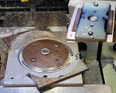
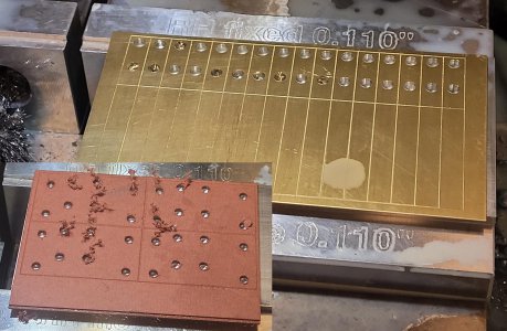
Next was the “HV” revolving contact unit. This subassembly includes a base board made from fiber insulation with a couple of common Erector set strips riveted to the ends for mounting brackets. A couple of brass contact strips are riveted/screwed to the fiber material. The subassembly is then riveted to the “AZ” bull ring plate. I did the fiber board and contacts on the Tormach. The routine for the fiber board scribed the periphery and drilled the rivet/screw holes. The routine for the contacts scribed the periphery/bend line and drilled the mounting holes. The parts were trimmed to size with a 4-ton notcher.
Fiber mounting board and brass contacts were roughed out on the Tormach. Used carpet tape to bond the stock to an aluminum plate.
The position of the holes for the two contact strips is somewhat critical relative to the bottom of the two support brackets as this sets the contact height relative to the bottom rotating plate. The contact strips should be centered on the “HZ” contact drums (though the drums have some up/down adjustment). I riveted flat strips to the fiber board and did the right-angle bends on the brake after the fact. Layout was a piece of tape with a line draw to eyeball the position.
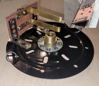
The contact subassembly is then riveted to the “AZ” plate. Gilbert didn’t use existing holes for the locations. I developed the location on an “AZ” and used that as my master for punching others. Screwed together the master and another “AZ” using the master as a guide for punching the holes on the RW 218 press. This may be another CNC job in the future; I make the “AZ” plates via CNC, it’d be pretty simple to add 4 additional drilled holes to the routine.
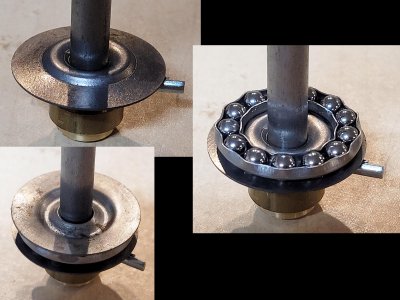
Next in the stack assembly was a couple of “HX” hub washers and a “HW” ball race; ball-bearing thrust washer at the bottom of the assembly. I bought some ball-bearing thrust washers off Amazon for the “HW” ball race but had to make the “HX” washers. The “HX” washers have an embossment to capture the “HW” ball race and a loose 5/16” hole to center them on the 5/16” axle. These were made from 0.036” steel; punched a 5/16” hole and bolted a stack of them together for turning to 1.25” OD on the lathe. They are the same size as the punch I use for the fiber disks, but alas that punch was made from stainless and is not hardened. I made a “mash die” from CRS to knock in the embossment. Used a 5/16” dowel pin to hold the blank in place and mashed away with a 20-ton press.
I didn't have a punch/die for the thrust washers. So, for a small number, turned blanks on a 5/16" bolt as a mandrel. Full disclosure is the HSS tool bit shown in the photos worked MUCH better than carbide insert tooling (didn't like the interrupted cut).
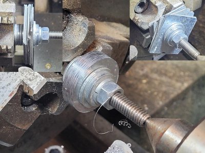
Photo of the bottom thrust bearing setup: The washers capture the center axle and hold the ball-thrust bearing more or less on center
The swivel unit rides on a 5/16” rod with an “HY” hub at the bottom. That’s the hub similar to the “BA” and “HZ” hubs except it has a through hole for a cotter pin. I figured out the length of the 5/16” rod by stacking the various components on a 5/16” bolt. Cut them on the bandsaw and drilled a couple of 1/8” cross-holes ½” from each end for cotter pins; did that on the BP.
Wiring back in 1929 was generally cotton-wrapped; found some suitable 2-strand 18-gauge wire off Amazon and some 2-prong plugs. I’m not an electrician and can’t speak to the current electrical code. That being said, I believe these units as designed might not meet current code as no ground wire is carried to the swivel, just the hot and common. Our daughter is an attorney, my future eBay listings for these will include a caveat that they are for display only and not intended to be actually plugged in (or whatever legalese is required). On the other hand, we have plenty of kitchen appliances (waffle iron, hand blender, stationary blender, etc.) that don’t carry ground, so maybe it is okay? After all, the Gilbert company did sell lead-soldier casting sets, electrical sets with mercury in vials, and an Atomic Energy set with radioactive samples! Maybe safety wasn’t #1, but it was in their top 100!
Gilbert soldered the plug wires to the surface of the two contact drums; I used a brass eyelet and soldered the leads in the hole. Not “period accurate”, but the two original units I’ve seen had their wiring separated from the drums. I’m thinking my method is a little more robust and definitely easier to repair if the wires get yanked on. The leads on the revolving contact unit are screwed to the “HV” contact unit and run down to the Zeppelin’s motor.
Next was making a couple of music wire loops to secure cables from the “HV” revolving contact unit down to the model. I had some spring stock on hand that worked for this; cut a couple of coils with side cutters.
Lastly, I used some picture hanging cable for the tethers that run to the Zeppelin’s structure. The ends were looped through a brass eyelet, mashed, and soldered.
First run of parts. It'll be the law of supply and demand from this point on. I've got about $20 in material cost per unit plus time. If the market supports only $30 a part, they'll be removed from the "production schedule".
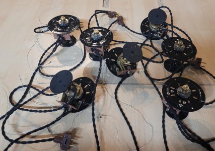
Photo of the components
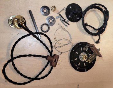
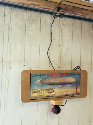
Photo from my eBay ad. I was too lazy to actually build the Zeppelin model, so went with this label and a motor spinning a prop mounted below to show the "IA" in use.
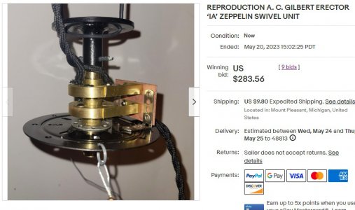
Here’s what the first one did on eBay before their fees. It takes two to take a $50 starting bid up to this; made a 2nd chance offer which was accepted. So now up to about $5 / hour for development time! This one won’t be a high-volume part, but it was shop time regardless.
Thanks for looking, Bruce
Germany’s Graf Zeppelin went on a round-the-world tour in 1929. The nearly 800’ long rigid airship was received with much awe during this tour. The A. C. Gilbert Company capitalized on the fervor by introducing an Erector set in 1929 that built a 5’ model of the Zeppelin. And “NO”, Gilbert did not include a canister of hydrogen to inflate their model! Here are a few manual pages showing the model.
Manual pages showing the construction of the 5' Zeppelin model. The Erector girder superstructure was covered with a cloth bag.


Here's the drawing of the "IA" swivel assembly and the components.

And a couple of photos of my reproduction


Gilbert offered an “only available from the factory” part number “IA” swivel assembly that hung the model from the ceiling and through a couple of contact drums brought 110V down to a motor in one of the gondolas to spin a propellor. This was a static display as the propellor/110V motor didn’t generate nearly enough wind to move the model. I suspect it was more for a store display. By the way, the “IA” swivel unit cost $2.50 from the factory back in 1929. I have seen TWO original swivel units in 25 years of collecting Erector sets; one in a collection, the other on eBay. I’ve had this one on my “to do” list for quite a few years and finally put in the time to make a few.
Projected volume influences the way I make these parts. CNC is nice, but if the volume in really low, it makes more sense to make up the components manually. I plan on making less than a dozen of them for a first run. If the volume warrants it, I’ll end up retooling some of the components that I currently do manually.
Gilbert was a master of repurposing existing parts to new applications. The part that I most struggled with was the “HZ” contact drums. These were made from brass and were secured to a central 5/16” rod with a brass hub. The hub was peened to a fiber disk which in turn was riveted to the “HZ” drum. The hub is identical to the bushing/plate riveted to the bottom support plate which is common Erector set part number “BA”. The fiber disk was 1 ¼” diameter which is also common with another Erector set part with a smaller hub that I make. Bonus! I got to share some tooling!
I tried making the drums by metal spinning but failed. Then tried to manually peen the brass disk over a mandrel heating it frequently to anneal the brass. Another failure. Third attempt was with a draw die that my father-in-law had for a similar steel part used on a toy wagon. The blanks kept splitting so I went with plan “D”: solder a disk inside of a piece of tubing. The drums are 1 ½” diameter with a 0.300” face and a bottom with a ¾” hole at the center. I bought some 0.040” thick seamless 1 ½” OD brass tubing off Amazon, chucked it up in the lathe and parted off 0.300” rings.
For the bottom plate, I used some 0.040” brass stock. These needed to be cut into disks with an OD of around 1.415” with a ¾” center hole. I thought about using carpet tape to secure the brass to an aluminum plate and drill/cut them on the CNC, but ended up with a very manual process. I’ll end up making around 24 of these, so the CNC route is looking good if I make more. I cut 1 ½” squares of brass, punched a ¾” hole, stacked them on a mandrel and turned the OD on the lathe. The drum bottoms have 4 holes on 1” centers at “12, 3, 6 and 9 o’clock” that are riveted to the fiber disk. For this, I turned a chunk of plastic with a bored 1 ½” ID hole. This piece went to the Bridgeport, found center with a Blake co-ax, and drilled holes for transfer punching the hole locations to the brass bottom.
Turned a double-ended mandrel with 1/2" and 3/4" shoulders and a 5/16"-18 center hole. My plan was to stack punched blanks on the mandrel, slip a clamping sleeve over the mandrel and bolt it down. Then turn to diameter on the lathe.

Here's a couple of brass blanks stacked on the 3/4" end of the mandrel. The OD of the brass is turned so around 1.415"; if I was making a pile of them I'd make a punch and die. But for a handful. . . The fiber material is turned down to 1.25" diameter; I found a punch/die this size so ended up not using the 1/2" end of the mandrel.

Brass tubing up top (parted off on the lathe) and turning some brass blanks to diameter.

Didn't show a lot of the ops here. Bored a piece of plastic to 1.5", found center on the Bridgeport with a Blake Co-ax, and drilled holes for transfer punching locations to the brass and fiber disks.

Then turned a second plastic piece to 1 ½” OD so the two plastic pieces nested together. The smaller piece has a shallow ¾” shoulder to center the brass disk for transfer punching. I did those holes with a RW No. 5 hand punch. After that, Scotchbrite’d the brass clean, applied a little flux and soldered them together.
Picture of the drums after punching the mounting holes in the brass bottom and fiber board. I didn't show it, but turned hubs from 5/8" brass with a 5/16" center hole for the main axle. Set the brass disk inside the brass drum and soldered in place. Used a steel ball and ball peen hammer to peen over the edge of the brass hubs to the fiber disks. Then used tubular rivets to attach the fiber disk to the drum. The fiber disk electrically isolates the hub from the brass drum.

The fiber disk has a center hole ½” diameter, OD is 1.25”. I have an unhardened punch & die I use for a similar Erector set part; no new tooling needed here! Knocked out the disks, punched the ½” center hole, and used a similar 1 ½” OD plastic piece with a ½” shoulder to center the disk in the transfer punch fixture.
Four hubs are used in each full assembly. The hubs are made from 5/8” diameter brass with shoulders on either end turned to ½” diameter. Three of these get an 8-32 tapped hole, while a fourth one gets a through-hole drilled for a cotter pin (and becomes part number “HY” hub). I made a drill bushing from 1” O-1 to do the 8-32 tap hole. The shoulder on the brass hub is ½” diameter with a 0.300” face. The tap hole is centered on the 0.300” face. Did the work there on the Bridgeport with a square collet. Tap drilling and tapping was done on the lathe with cordless drills. The three hubs that get peened to brass or steel disks get a countersink on the back side to facilitate peening. Peening was done with a holding fixture, a big steel ball, and a 2 lb. ball peen hammer. The steel disk used in the bottom “BA” part came from recycled existing Erector set part number “BT”. Chucked those on the lathe, and used a countersink to remove the peened hub. The disks have a 9/32” hole which was opened to ½”. These were drilled out on the lathe using a 5-C emergency collet to grip the OD. Sorry, didn't have pictures of any of this.
Next was the “HT” ceiling support. I made these from 1/8” steel plate and a 5/8” diameter steel round which were welded together to make a part that resembles a pipe flange. I used the Tormach to make the 1/8” round plate and drill the ceiling mounting holes. The 5/8” steel rod was drilled out on the lathe for the 5/16” axle rod, and a 1/8” long shoulder at ½” diameter turned for nesting into the disk. Then over to the BP to drill a cross-hole for a cotter pin. Couple of hits with the Hobart MIG welder, then add a fillet of JB Weld, clean up the fillet on the lathe and paint.
Cut the blanks from 3" wide 1/8" CRS and drilled a 1/2" center hole on the BP. Did the four mounting holes on the Tormach. Also cut the squares into circles on the Tormach.

Didn't show the lathe or welding work. Drilled a 5/16" hole through 5/8" CRS and turned an 1/8" deep shoulder to 1/2" diameter. Bolted the rod into the disk and tacked them together. Then built up a fillet with JB Weld. Cleaned up the fillet on the lathe with a rat-tail file.

Next was the “HV” revolving contact unit. This subassembly includes a base board made from fiber insulation with a couple of common Erector set strips riveted to the ends for mounting brackets. A couple of brass contact strips are riveted/screwed to the fiber material. The subassembly is then riveted to the “AZ” bull ring plate. I did the fiber board and contacts on the Tormach. The routine for the fiber board scribed the periphery and drilled the rivet/screw holes. The routine for the contacts scribed the periphery/bend line and drilled the mounting holes. The parts were trimmed to size with a 4-ton notcher.
Fiber mounting board and brass contacts were roughed out on the Tormach. Used carpet tape to bond the stock to an aluminum plate.

The position of the holes for the two contact strips is somewhat critical relative to the bottom of the two support brackets as this sets the contact height relative to the bottom rotating plate. The contact strips should be centered on the “HZ” contact drums (though the drums have some up/down adjustment). I riveted flat strips to the fiber board and did the right-angle bends on the brake after the fact. Layout was a piece of tape with a line draw to eyeball the position.

The contact subassembly is then riveted to the “AZ” plate. Gilbert didn’t use existing holes for the locations. I developed the location on an “AZ” and used that as my master for punching others. Screwed together the master and another “AZ” using the master as a guide for punching the holes on the RW 218 press. This may be another CNC job in the future; I make the “AZ” plates via CNC, it’d be pretty simple to add 4 additional drilled holes to the routine.
Next in the stack assembly was a couple of “HX” hub washers and a “HW” ball race; ball-bearing thrust washer at the bottom of the assembly. I bought some ball-bearing thrust washers off Amazon for the “HW” ball race but had to make the “HX” washers. The “HX” washers have an embossment to capture the “HW” ball race and a loose 5/16” hole to center them on the 5/16” axle. These were made from 0.036” steel; punched a 5/16” hole and bolted a stack of them together for turning to 1.25” OD on the lathe. They are the same size as the punch I use for the fiber disks, but alas that punch was made from stainless and is not hardened. I made a “mash die” from CRS to knock in the embossment. Used a 5/16” dowel pin to hold the blank in place and mashed away with a 20-ton press.
I didn't have a punch/die for the thrust washers. So, for a small number, turned blanks on a 5/16" bolt as a mandrel. Full disclosure is the HSS tool bit shown in the photos worked MUCH better than carbide insert tooling (didn't like the interrupted cut).

Photo of the bottom thrust bearing setup: The washers capture the center axle and hold the ball-thrust bearing more or less on center

The swivel unit rides on a 5/16” rod with an “HY” hub at the bottom. That’s the hub similar to the “BA” and “HZ” hubs except it has a through hole for a cotter pin. I figured out the length of the 5/16” rod by stacking the various components on a 5/16” bolt. Cut them on the bandsaw and drilled a couple of 1/8” cross-holes ½” from each end for cotter pins; did that on the BP.
Wiring back in 1929 was generally cotton-wrapped; found some suitable 2-strand 18-gauge wire off Amazon and some 2-prong plugs. I’m not an electrician and can’t speak to the current electrical code. That being said, I believe these units as designed might not meet current code as no ground wire is carried to the swivel, just the hot and common. Our daughter is an attorney, my future eBay listings for these will include a caveat that they are for display only and not intended to be actually plugged in (or whatever legalese is required). On the other hand, we have plenty of kitchen appliances (waffle iron, hand blender, stationary blender, etc.) that don’t carry ground, so maybe it is okay? After all, the Gilbert company did sell lead-soldier casting sets, electrical sets with mercury in vials, and an Atomic Energy set with radioactive samples! Maybe safety wasn’t #1, but it was in their top 100!
Gilbert soldered the plug wires to the surface of the two contact drums; I used a brass eyelet and soldered the leads in the hole. Not “period accurate”, but the two original units I’ve seen had their wiring separated from the drums. I’m thinking my method is a little more robust and definitely easier to repair if the wires get yanked on. The leads on the revolving contact unit are screwed to the “HV” contact unit and run down to the Zeppelin’s motor.
Next was making a couple of music wire loops to secure cables from the “HV” revolving contact unit down to the model. I had some spring stock on hand that worked for this; cut a couple of coils with side cutters.
Lastly, I used some picture hanging cable for the tethers that run to the Zeppelin’s structure. The ends were looped through a brass eyelet, mashed, and soldered.
First run of parts. It'll be the law of supply and demand from this point on. I've got about $20 in material cost per unit plus time. If the market supports only $30 a part, they'll be removed from the "production schedule".

Photo of the components

Photo from my eBay ad. I was too lazy to actually build the Zeppelin model, so went with this label and a motor spinning a prop mounted below to show the "IA" in use.

Here’s what the first one did on eBay before their fees. It takes two to take a $50 starting bid up to this; made a 2nd chance offer which was accepted. So now up to about $5 / hour for development time! This one won’t be a high-volume part, but it was shop time regardless.

Thanks for looking, Bruce
Last edited:

