- Joined
- Nov 23, 2014
- Messages
- 2,607
Back with another reproduction Erector set part string. This one is a two for one: Erector set airplane part number “GE” and Zeppelin part number “HJ” propeller blades. First, the obligatory history lesson. . .
Gilbert introduced the No. C Airplane set in 1928. The included parts could build a number of different airplane models: Biplane, monoplane, 1/2/3 engine(s), float plane, etc. The sets came with three part number “GE” propellers. These were made from 0.020” sheet metal and were 7” long x 5/8” wide. In 1929, Gilbert introduced the Zeppelin model which included three part number “HJ” propeller blades. These were similar to the “GE” props, but were 4 ½” long x 5/8” wide.
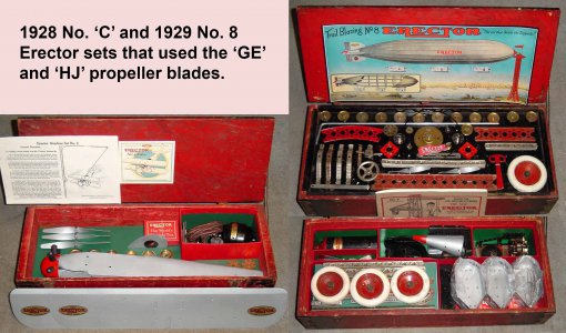
I don’t expect these to be big sellers as the Airplane set was a very poor seller back in the day. I’ve seen maybe THREE of them on eBay over the last 20 years. The Zeppelin set sold much better; I’ve seen around 100 of these sets over the years. What I’m going after is a guy/gal with an incomplete set who needs these parts. Or, a parts hoarder who wants spares just in case they find an incomplete set.
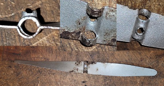
If it’s such a small market, why make the parts? You’ll see in the photos how the props attached to the 5/32” axle; no brass hub like typical Erector set parts. Instead, they did a “push me, pull me” on the sheet metal to form a hole for the axle; three “U’s” with alternating orientation to form a “O”. The middle “U” had a hole pierced in the sheet metal and was threaded for a set screw. I did this part mainly for the shop time and maybe learn something. Plus, I have a 1929 No. 10 set with reproduction props by an unknown maker (no, wasn’t me!) who did a terrible job. Time to refresh the set before I sell it.
This is an original 'GE' airplane prop. A 5/32" axle slips through the hole and is fastened with a 6-32 set screw
The axle attachment dies would be the biggest challenge in this part. The “GE” and “HJ” were the same width and used the same 5/32” axle so the tooling to form the axle feature could be shared on both parts. I doubt I’ll sell many of the “GE” blades, but made up a handful just in case.
I envisioned a die set with 3 shearing/forming “rods”. A center one would pass by two outer ones to shear the sheet metal blank and form the opposing “U’s” leaving an axle hole.
I made the dies by stacking 3 pieces of steel per side. The center “U” is 3/8” wide; grabbed a length of CRS 3/8” wide for the punch/die. Butted two plates of steel together, then drill an 11/64” hole through where they meet. This gave me two pieces with a half-11/64” hole on the edge. The punch side would get a piece of 11/64” drill rod silver soldered in place; grind the overlap flush to the block. The mating side would have a #3 (or whatever size it was) hole drilled for clearance for the 0.020” stock.
I made the outer dies from ½” stock; same process as the center one except the 11/64” half-holes for the shear pins would be on the opposite side. All of the die blocks were drilled and reamed with an oversized ¼” reamer for alignment.
Top and bottom dies are each made from a stack of 3 blocks. Started by milling the blocks to size, then drilled and reamed oversize 1/4" holes for doweling the stacks together.
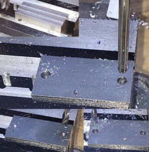
Set pairs of blocks face to face, spot drilled and drilled 11/64" and/or #3 holes for forming pins or clearance. This left the two blocks with 1/2 holes across the face.
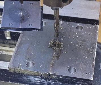
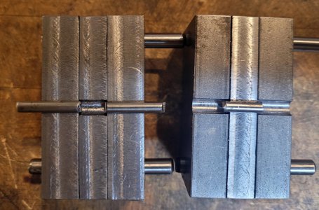
Dies with the 11/64" drill rod loosely set in place. The drill rod was silver soldered to the blocks and hardened. The 11/64" drill rod block will nest into the opposing block with a #3 half-hole (provides clearance for the 0.020" thick sheet steel). The rods on the upper/lower die will shear the sheet metal as they pass by each other.
My original plan was to mount the lower die in the stock Roper Whitney die holder. But, another case of me not planning things out well. . . The 3/8” & ½” bar stock I had on hand was 1 ½” wide. The resulting stack of the dies would end up being about ½” taller than would fit in my #218 press. Yeah, I could have taken ½” of a combo of the top/bottom dies, but went a different approach. Plan B was to machine a carrier block for the lower die that bolts to a ½” plate I had on hand for another die.
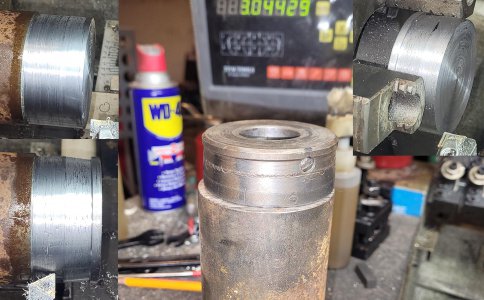
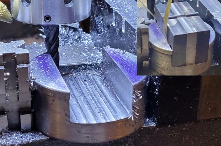
Turned a 3” round to 2 ¾”, cut off on the band saw, and faced the cut off side on the lathe. Then over to the Bridgeport to mill out a trough 0.7” deep by 1.390” wide. The lower die set is 1.375” wide (plus some shims explained below), so went 0.015” wider on the trough. My BP has a 2-axis CNC setup; so nice to fire up the routine and walk away! After the trough was done, drilled and tapped a set screw hole in the die carrier to clamp and position the lower die stack together.
Stock bottom die holder on top of a 3" round. Turned a similar piece for the lower die.
Plowing a trough for the 1 3/8" (plus a little for shim stock) lower die holder. The lower die would have some shim stock between the plates to provide a little clearance as the top die meshes into the lower.
On to the dies themselves. Erector set axles are 5/32” diameter. Anticipating a little spring back, plan was to form the “U’s” with 11/64” stock. I didn’t show it, but silver soldered chunks of an 11/64” drill bit in the drilled troughs. Then ground the overhang to flush with the faces of the 3/8” and ½” thick steel carriers.
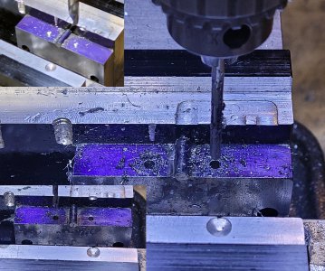
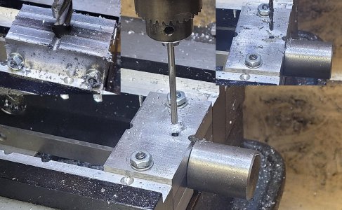
The lower die set has the outer shearing rods, upper die the center one. I drilled a couple of holes in the lower die for blank aligning pins; just there to position the blank. The upper had corresponding clearance holes drilled to clear the alignment pins as the dies mesh.
Knocking in a couple of 1/8" pin holes to position the prop blade blank in the die
The upper die had a ½” hole bored in the center to attach a 1” round which in turn was used to secure the upper die in the punch press. The upper die stack and 1” round were doweled together.
Bored a 1/2" hole in the top of the upper die for attaching a 1" rod. Didn't show the lathe work, but turned a shoulder on 1" stock to fit into the upper die. Then back to the BP to drill/dowel an attaching pin.
The upper and lower dies need a little clearance where the shear/forming pins pass over each other. Punch/die clearance is usually 15% of material thickness for mild steel. I was using 0.020” stock, so a total of 0.003” clearance or 0.0015” per side. I went a little conservative here and used 0.004” shim stock between the ½” and 3/8” plates of the lower die. If the “U’s” showed a burr, I’d sub in some thinner shim stock.
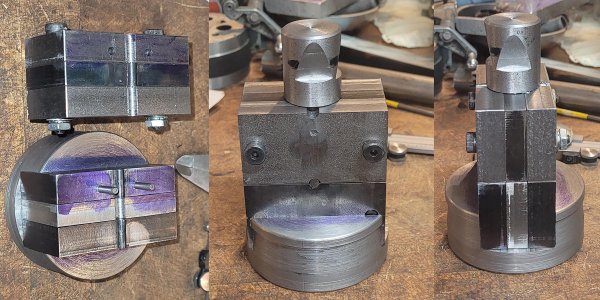
Finished dies.
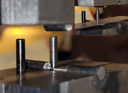
The upper chunk of 11/64" drill rod passes by the two lower pieces and shears the sheet metal. Also, presses in alternating "U's" leaving a hole for the 5/32" axle.
Next was the pierced hole for the 6-32 set screw. My plan was to punch the hole, then tap with a roll-form tap. Reasoning being, there wouldn’t be a lot of stock there so roll forming seemed to be the best option.
Turned some ½” O-1 for a punch at 0.122” diameter (drill size for a roll form 6-32 tap). The tip is at a point for piercing the blank. The bottom die was a piece of 3/8” CRS with the #3 cross-hole. Drilled a clearance hole for the punch on the BP. Clearance hole was 0.122” plus 0.040” for the blank stock. The punch has a shoulder turned to that diameter upstream from the 0.122” diameter to position the punch/die in the punch press (center the punch on the hole in the die). Machined a couple of pieces of ½” thick aluminum for a 1 3/8” wide stack; one piece is just sub-flush to the top of the “U”. In use, I’d set the formed blank in the lower die and shove it up against the aluminum block (center the “U” on the die) for centering the “U” in the die.
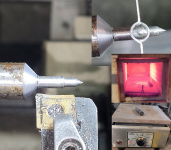
Punch for the extruded/pieced hole. Sharp point on the end pierces the 0.020" blank, shank is 0.122" beyond that leaving a 0.122" hole in the sheet metal. The larger diameter upstream from the 0.122" area fits into the lower die for set up purposes (centers the punch to the die). Hardened and tempered the punch.
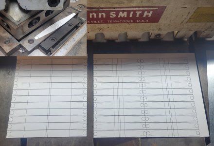
The blanks were very crudely cut. Layout work is time consuming when there are multiples to make. I use a couple of methods for transferring the pattern: either a CNC routine and diamond-drag engrave on the stock on my Tormach, or do a paper pattern which is glued to the stock. I went with the paper method here.
The prop blade blanks were cut to width on my Tennsmith shear. The taper on the ends of the blades were done on a 4-ton notcher. Radius on the ends were done on a belt sander.
Paper pattern was spray adhesived to the 0.020" sheet metal. Trimmed to the line with shears, radius on the end sanded to the line.
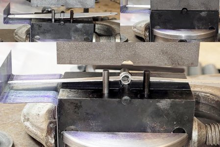
Then over to the Roper Whitney 218 press. Knocked in the axle holes; that went really well. I made a crude work stop of bent sheet metal to center the blades though having the layout lines on the part made this redundant.
Set the blank in place between the dies, pull up against the locating pins (set the edge), butt up against the stop on the left and pull down on the press.
After knocking in the axle feature, changed the set up on the RW 218 to the pierced/extruded hole. Then threaded with a roll-form tap in a cordless drill. String ‘em up on a wire, dust with gray primer and paint silver. Wish me luck on eBay!
Replaced axle-hole forming dies with the hole-pierce punch/die. Set a formed blank up against the stop and pull down on the punch. Hit the extruded hole with a roll form 6-32 tap in a cordless driver.
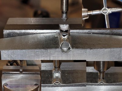
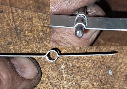
"Quality control" check before painting; verify the 5/32" axle loosely fits in the blade and run in a 6-32 screw. String them up on a wire, prime and paint.
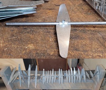
Thanks for looking, Bruce
Gilbert introduced the No. C Airplane set in 1928. The included parts could build a number of different airplane models: Biplane, monoplane, 1/2/3 engine(s), float plane, etc. The sets came with three part number “GE” propellers. These were made from 0.020” sheet metal and were 7” long x 5/8” wide. In 1929, Gilbert introduced the Zeppelin model which included three part number “HJ” propeller blades. These were similar to the “GE” props, but were 4 ½” long x 5/8” wide.

I don’t expect these to be big sellers as the Airplane set was a very poor seller back in the day. I’ve seen maybe THREE of them on eBay over the last 20 years. The Zeppelin set sold much better; I’ve seen around 100 of these sets over the years. What I’m going after is a guy/gal with an incomplete set who needs these parts. Or, a parts hoarder who wants spares just in case they find an incomplete set.
If it’s such a small market, why make the parts? You’ll see in the photos how the props attached to the 5/32” axle; no brass hub like typical Erector set parts. Instead, they did a “push me, pull me” on the sheet metal to form a hole for the axle; three “U’s” with alternating orientation to form a “O”. The middle “U” had a hole pierced in the sheet metal and was threaded for a set screw. I did this part mainly for the shop time and maybe learn something. Plus, I have a 1929 No. 10 set with reproduction props by an unknown maker (no, wasn’t me!) who did a terrible job. Time to refresh the set before I sell it.
This is an original 'GE' airplane prop. A 5/32" axle slips through the hole and is fastened with a 6-32 set screw

The axle attachment dies would be the biggest challenge in this part. The “GE” and “HJ” were the same width and used the same 5/32” axle so the tooling to form the axle feature could be shared on both parts. I doubt I’ll sell many of the “GE” blades, but made up a handful just in case.
I envisioned a die set with 3 shearing/forming “rods”. A center one would pass by two outer ones to shear the sheet metal blank and form the opposing “U’s” leaving an axle hole.
I made the dies by stacking 3 pieces of steel per side. The center “U” is 3/8” wide; grabbed a length of CRS 3/8” wide for the punch/die. Butted two plates of steel together, then drill an 11/64” hole through where they meet. This gave me two pieces with a half-11/64” hole on the edge. The punch side would get a piece of 11/64” drill rod silver soldered in place; grind the overlap flush to the block. The mating side would have a #3 (or whatever size it was) hole drilled for clearance for the 0.020” stock.
I made the outer dies from ½” stock; same process as the center one except the 11/64” half-holes for the shear pins would be on the opposite side. All of the die blocks were drilled and reamed with an oversized ¼” reamer for alignment.
Top and bottom dies are each made from a stack of 3 blocks. Started by milling the blocks to size, then drilled and reamed oversize 1/4" holes for doweling the stacks together.

Set pairs of blocks face to face, spot drilled and drilled 11/64" and/or #3 holes for forming pins or clearance. This left the two blocks with 1/2 holes across the face.

Dies with the 11/64" drill rod loosely set in place. The drill rod was silver soldered to the blocks and hardened. The 11/64" drill rod block will nest into the opposing block with a #3 half-hole (provides clearance for the 0.020" thick sheet steel). The rods on the upper/lower die will shear the sheet metal as they pass by each other.

My original plan was to mount the lower die in the stock Roper Whitney die holder. But, another case of me not planning things out well. . . The 3/8” & ½” bar stock I had on hand was 1 ½” wide. The resulting stack of the dies would end up being about ½” taller than would fit in my #218 press. Yeah, I could have taken ½” of a combo of the top/bottom dies, but went a different approach. Plan B was to machine a carrier block for the lower die that bolts to a ½” plate I had on hand for another die.
Turned a 3” round to 2 ¾”, cut off on the band saw, and faced the cut off side on the lathe. Then over to the Bridgeport to mill out a trough 0.7” deep by 1.390” wide. The lower die set is 1.375” wide (plus some shims explained below), so went 0.015” wider on the trough. My BP has a 2-axis CNC setup; so nice to fire up the routine and walk away! After the trough was done, drilled and tapped a set screw hole in the die carrier to clamp and position the lower die stack together.
Stock bottom die holder on top of a 3" round. Turned a similar piece for the lower die.

Plowing a trough for the 1 3/8" (plus a little for shim stock) lower die holder. The lower die would have some shim stock between the plates to provide a little clearance as the top die meshes into the lower.

On to the dies themselves. Erector set axles are 5/32” diameter. Anticipating a little spring back, plan was to form the “U’s” with 11/64” stock. I didn’t show it, but silver soldered chunks of an 11/64” drill bit in the drilled troughs. Then ground the overhang to flush with the faces of the 3/8” and ½” thick steel carriers.
The lower die set has the outer shearing rods, upper die the center one. I drilled a couple of holes in the lower die for blank aligning pins; just there to position the blank. The upper had corresponding clearance holes drilled to clear the alignment pins as the dies mesh.
Knocking in a couple of 1/8" pin holes to position the prop blade blank in the die

The upper die had a ½” hole bored in the center to attach a 1” round which in turn was used to secure the upper die in the punch press. The upper die stack and 1” round were doweled together.
Bored a 1/2" hole in the top of the upper die for attaching a 1" rod. Didn't show the lathe work, but turned a shoulder on 1" stock to fit into the upper die. Then back to the BP to drill/dowel an attaching pin.

The upper and lower dies need a little clearance where the shear/forming pins pass over each other. Punch/die clearance is usually 15% of material thickness for mild steel. I was using 0.020” stock, so a total of 0.003” clearance or 0.0015” per side. I went a little conservative here and used 0.004” shim stock between the ½” and 3/8” plates of the lower die. If the “U’s” showed a burr, I’d sub in some thinner shim stock.
Finished dies.

The upper chunk of 11/64" drill rod passes by the two lower pieces and shears the sheet metal. Also, presses in alternating "U's" leaving a hole for the 5/32" axle.


Next was the pierced hole for the 6-32 set screw. My plan was to punch the hole, then tap with a roll-form tap. Reasoning being, there wouldn’t be a lot of stock there so roll forming seemed to be the best option.
Turned some ½” O-1 for a punch at 0.122” diameter (drill size for a roll form 6-32 tap). The tip is at a point for piercing the blank. The bottom die was a piece of 3/8” CRS with the #3 cross-hole. Drilled a clearance hole for the punch on the BP. Clearance hole was 0.122” plus 0.040” for the blank stock. The punch has a shoulder turned to that diameter upstream from the 0.122” diameter to position the punch/die in the punch press (center the punch on the hole in the die). Machined a couple of pieces of ½” thick aluminum for a 1 3/8” wide stack; one piece is just sub-flush to the top of the “U”. In use, I’d set the formed blank in the lower die and shove it up against the aluminum block (center the “U” on the die) for centering the “U” in the die.
Punch for the extruded/pieced hole. Sharp point on the end pierces the 0.020" blank, shank is 0.122" beyond that leaving a 0.122" hole in the sheet metal. The larger diameter upstream from the 0.122" area fits into the lower die for set up purposes (centers the punch to the die). Hardened and tempered the punch.

The blanks were very crudely cut. Layout work is time consuming when there are multiples to make. I use a couple of methods for transferring the pattern: either a CNC routine and diamond-drag engrave on the stock on my Tormach, or do a paper pattern which is glued to the stock. I went with the paper method here.
The prop blade blanks were cut to width on my Tennsmith shear. The taper on the ends of the blades were done on a 4-ton notcher. Radius on the ends were done on a belt sander.
Paper pattern was spray adhesived to the 0.020" sheet metal. Trimmed to the line with shears, radius on the end sanded to the line.

Then over to the Roper Whitney 218 press. Knocked in the axle holes; that went really well. I made a crude work stop of bent sheet metal to center the blades though having the layout lines on the part made this redundant.
Set the blank in place between the dies, pull up against the locating pins (set the edge), butt up against the stop on the left and pull down on the press.

After knocking in the axle feature, changed the set up on the RW 218 to the pierced/extruded hole. Then threaded with a roll-form tap in a cordless drill. String ‘em up on a wire, dust with gray primer and paint silver. Wish me luck on eBay!
Replaced axle-hole forming dies with the hole-pierce punch/die. Set a formed blank up against the stop and pull down on the punch. Hit the extruded hole with a roll form 6-32 tap in a cordless driver.

"Quality control" check before painting; verify the 5/32" axle loosely fits in the blade and run in a 6-32 screw. String them up on a wire, prime and paint.

Thanks for looking, Bruce

