-
Welcome back Guest! Did you know you can mentor other members here at H-M? If not, please check out our Relaunch of Hobby Machinist Mentoring Program!
You are using an out of date browser. It may not display this or other websites correctly.
You should upgrade or use an alternative browser.
You should upgrade or use an alternative browser.
Erl-1340
- Thread starter pstemari
- Start date
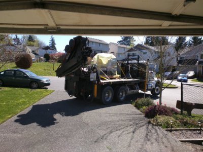
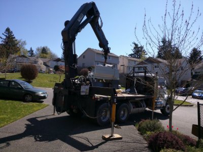
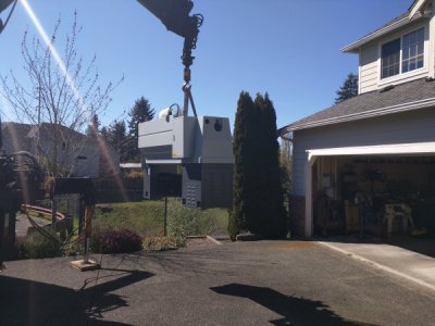
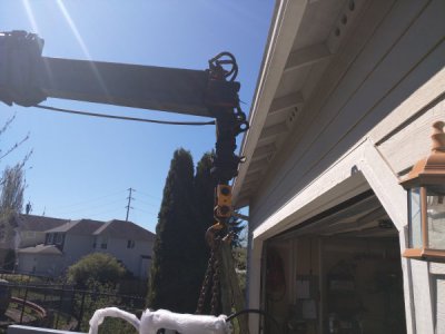
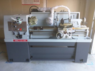
Weight's about one ton.
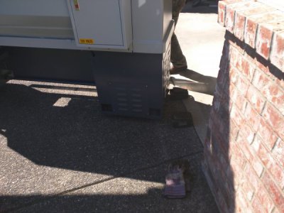
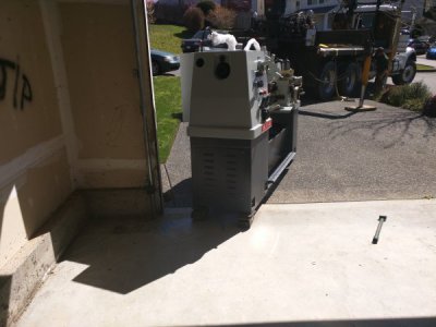
Shipping it directly to the rigger was the easiest way to handle it, especially since it's too heavy for a lift gate and the shipping company only had a rough delivery date. Total charge for the rigger was $600, pretty fair for unloading it off the truck, hauling it from Mt Vernon to Renton, and placing it in the garage.
Sent from my Nexus 6 using Tapatalk
- Joined
- Dec 1, 2014
- Messages
- 56
Dang am I drooling. But I totally agree. When you have that kind of money invested into a machine that size $600 seems cheap to ensure it gets placed in one piece and not several busted pieces for less $$. I sure hope you post some youtube videos of that baby in action. I'd love to see it and hear your impression of it.  GRATZ!!!
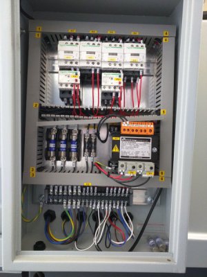
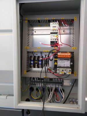
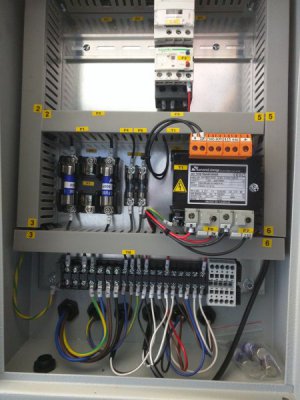
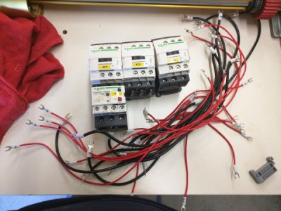
Started pulling out the contactors for the VFD conversion. The Hitachi is a wee bit too big to fit in the electrical cabinet, and the front panel lacks enough room for adding a key switch, jog direection, and speed pot, so I bought a Bud NEMA 4 enclosure from Amazon to house everything.
Plan is to put a frequency meter, key switch, e-stop, jog button, jog direction switch, indicator lamp, coolant switch, and speed pot on the front of the added cabinet, and keep the existing front panel controls wired in series (e-stop) or parallel (jog button, coolant switch) as appropriate.
A few pics of the cabinet and stuff removed:


- Joined
- Jun 12, 2014
- Messages
- 4,817
I have built control box extensions for the cover panel when the VFD did not fit. I had some phenolic impregnated CE board that I used, but just about anything will work. Probably want to extend it to around 8". You could probably dump the big transformer for a more compact 24VDC unit if you choose to go that route and plan to use smaller control relays. Surprised you do not have enough room on the front panel, did a recent build on a 1440 lathe, and was able to fit everything in, but the speed readout was put up above under the DRO. I like thisposition, as it is easily seen when operating the machine. You can combine functions, so the power on light can be in the E-Stop or use a lighted Jog.Have been using a joystick for individuals that want forward/reverse jog feature.
One awesome machine, will be a monster once you add the VFD. A perfect combination.
One awesome machine, will be a monster once you add the VFD. A perfect combination.
The front panel is constrained by the casting—you can't add anything on the sides because the gap in the casting is about five inches narrower than the panel.
The transformer also runs the coolant pump (1ph 120VAC). I considered connecting that directly to the mains, but decided that the isolation provided by the xfmr was a desirable safety feature.
Sent from my Nexus 6 using Tapatalk
The transformer also runs the coolant pump (1ph 120VAC). I considered connecting that directly to the mains, but decided that the isolation provided by the xfmr was a desirable safety feature.
Sent from my Nexus 6 using Tapatalk
Getting the cabinet extension for the vfd set up. There's nuts on the back side of the mounting panel—I'm mulling over the option of tack welding then to the panel to make it easier to unmount/remount things. I don't think solder or epoxy would work very well. Another option would be to put the screw heads in back and add an extra nut to hold the screws in permanently.


