Failed Miserable At Cutting A Disc Brake Rotor

Hi jmarkwolf,

Lots of great input above. I also agree that the keys are rigidity and cutting speed.
Both will be impacted by what diameter you are cutting on this disc.
The outer diameter is further from the supporting axle and is also moving faster.

With respect to the latter, for me it always helps me to think about the cutting speed in surface feet per min (sfpm). I always look up the recommended cutting speeds in sfpm for the material and tool I am using. Then use the diameter (of the work on the lathe or cutter on the mill) to determine RPM to run the machine.

sfpm ~= rpm x dia.(in inches) /4

So, for the same rpm, if you double the diameter you also double the cutting speed in sfpm.
For facing large diameter work, use the rpm calculated at the outside dia.

Pure speculation as I have never done it, but this might be a suitable project for some kind of electric/magnetic braking system. You could remove any changes in mechanical surface finish of brake pad and disc completely from the equation.

Good Luck!
-brino
 
I think your system will vary as the disc heats up.

I have worked on two smaller dynamometer setups. The larger one used a generator and output directly in watts. That was a ling time ago and I can't remember how the load was varied.

The second was modified from a go kart water-brake style dyno. This used a vane pump that could be throttled with a needle valve. I think it measured the torque from the free-floating pump with a load cell on an arm. You might check out go kart dynos to get ideas. Dennis
 
For your application, a band brake would be better suited

I like this idea. Like a leather strap anchored on one end and runs over a wheel attached to you shaft, the other end with an attached pan to hold weights. The more weight the more drag. 1800's style dynomometer.
 
just buy a bike brake disk and make an appropriate hub. The cheap Shimano disks are ~$20 and mostly run true. I'd get a 6 bolt on and turn a hub out of a piece of alu. I wouldn't even consider trying to turn a brake disk, they're are SUPER hard.
 
As intimated earlier, you need to hold the disk in the lathe by it's outer diameter not by the shaft or near the center. The thing will sing like crazy and cut badly. Most of the time disks are too large to be held that way. Might be able to fab some kind of "ring" to be jammed between the chuck and the outer dia of the disk when the chuck is tightened ?? I tried cleaning up a rotor once and finally wound up using a modified tool post grinder and very light cuts....still wasn't really pleased with the result.
 
I think your system will vary as the disc heats up.

I have worked on two smaller dynamometer setups. The larger one used a generator and output directly in watts. That was a ling time ago and I can't remember how the load was varied.

The second was modified from a go kart water-brake style dyno. This used a vane pump that could be throttled with a needle valve. I think it measured the torque from the free-floating pump with a load cell on an arm. You might check out go kart dynos to get ideas. Dennis

I do a lot of work with a local hydraulic shop an that's how they dyno test hydraulic motors; They couple a motor to a pump, and control the torque by varying a pressure relief on the pump output.

It's a good system, and I want to build one of my own some day, probably using a power steering pump.

But if you're going that route to escape heat variance, note that this setup requires a pressure relief valve (Vs. a simple needle valve) to consistently function or else you're subject to the same variance due to heat. Forcing fluid through an orifice generates heat; lots of heat - it's the same amount of resistive work as a disk brake would be doing, and lubricating fluid medium be damned, the same quantity of friction and heat as a disk brake would generate. As hyraulic fluid heats up, it's viscosity changes. In a closed loop system with heat ever increasing, viscosity will be ever decreasing. As viscosity decreases, it takes less pressure (torque) to force it through a fixed size orifice. That's where the pressure relief comes in; it doesn't care about viscosity. Set the spring to relieve at 500PSI, it relieves at 500PSI whether you're pumping molasses or water. Think of it as torque regulator.

Also, if you're going to be running the hydraulic dyno long-term, it would be a good idea to install a fluid cooler whether using a needle valve or pressure relief valve. With all the heat building up faster than flat tank walls can dissipate it, you'll cook seals in the pump
 
Years ago on plastic printing machnies we used to use a 2 x 4 with a hole for the shaft and slotted so a bolt could tighten it up on the shaft. That would create enough drag on the shafts so plastic roll would not unroll if machine was stopped.
 
Brake rotor lathes are made to turn cast iron, that rotor is steel. You'll never clean that up on a lathe at this point. If you want to salvage it, surface grind it.
 
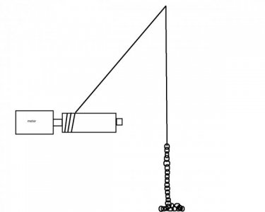
last time I needed to rate motors we did this...

the weight increases as more chain is pulled up off the floor..we simply counted links for comparison ...(till the motor stalled)


motor hooked to a tube pulley using rope to the chain

chain.jpg
 
Back
Top