Feeding a VFD with 3 phase input?

Senna

Deceased
Rest In Peace
Joined
Nov 3, 2013
Messages
405
I bought an AB Ultra 3000 multi-axis servomotor controller which is essentially a fancy VFD from Charley Davidson.

The issue I have is how to feed it three phase power it likes. The manufacturer of the RPC I have Jim at Phase-Craft thinks that the AB won't like the manufactured three phase from an RPC because there will be two 120v legs from the line input while the manufactured leg will be 220 or so. I don't understand this but Jim is a pretty smart guy who makes a great product.
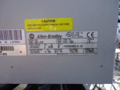
The AB I'm getting requires 120-240 three phase.

How do I configure this to work with an RPC?

Here's a picture of the data plate on the AB U3000
Allen Bradley 3000 (3).jpg

Allen Bradley 3000 (3).jpg
 
I'm going to go out on a limb a bit here, never having tried this before. Coming out of the RPC should be about 240V between the 3 phases, with one phase not quite 120 degrees with respect to the other 2 phases. The only place you should have 120V is from the 2 incoming power wires with respect to the neutral, which is not used in this system. Make sure the chassis is properly grounded per the wiring diagram on page B-5, in the installation manual.

Having said that, the VFD converts the incoming power to DC through the 3 phase bridge diode. If there is no phase monitoring on the input then I'm guessing it should work ok. If it doesn't like a unbalanced phase, I'm not sure what to do.

http://literature.rockwellautomation.com/idc/groups/literature/documents/in/2098-in003_-en-p.pdf

You're correct. The synthetic phase will be a little bit off (it can be fixed up with capacitors) but close enough. There is a neutral inside the RPC where the windings connect together that is what the three-phase voltages should be referred to, but it is not normally brought out (and you don't usually need it).
 
Here's what Jim wrote to me. (I mistakenly called him Jerry in a post, hence the last line.)

It's all Greek to me but maybe you knowledgeable guys can make sense of it.


That's definitely a VFD, and it looks like it needs the neutral,
although I'm not sure why. I can't say for sure that it'll work by
just picking up the neutral from the single phase side. The reason it
might not, is the output from a rotary phase converter is always a
delta output. That means the voltage from two of the phases to
neutral will be 120, but the third generated leg will be 208. My
guess is that the VFD won't like that. The only way around that is to
add a transformer on the output that will give you a wye output with
the neutral. That way will give you the same voltage from any phase
to neutral, but might make it too expensive to be worth doing if you
have other alternatives.

-Jerry... I mean Jim!

According to the wiring diagram for the AB Ultra 3000, the only place the neutral is only used in the 120V single phase model (2098-DSD-030x-xx). In the 240V 3 phase model (2098-DSD-075x-xx), the neutral is not used in the power circuit, it is shown being grounded. See pages B-4 and B-5 in the installation manual. As John stated, I'm pretty sure your RPC does not bring the neutral out.

Let me expand a bit on the inner workings of the VFD: The incoming power is converted to DC and then is fed to the output section and converted to 3 phase AC at a variable voltage and frequency to control the motor speed. The output section does not really know what is going on at the input section unless the control circuity is looking for phase drop or something like that. This is not a full description of how a VFD works, but rather just a quick overview of the operating principal.

Some VFD,s will take 120VAC single phase in, and output 240VAC, 3 phase. The 120 to 240 units I have used are limited to 1 HP max output. There may be others that have higher HP rating.
 
Jim, your help has been greatly appreciated and I hope you won't mind if I bend your ear a bit when I get the AB in my possession.
 
Jim, your help has been greatly appreciated and I hope you won't mind if I bend your ear a bit when I get the AB in my possession.


My pleasure, that's what this forum is all about. I'm always happy to help when I can.
 
Back
Top