Ferrite rings, educate me on their use

alloy

Dan, Retired old fart
H-M Supporter Gold Member
Joined
Jul 5, 2014
Messages
2,772
I have a holley sniper stand alone fuel injection unit on my 55 chevy. It's already been installed and on first startup it leaked so bad it covered my intake manifold. So Holley made me a deal to upgrade to a newer unit. I will be approximately mid next month for it to arrive.

After I had the problem with the fuel leak I joined a couple of forums and read up on the sniper injection and found people have a lot of problems with them, mostly of their own doing from wiring and other things. I did read one knowledgeable person on what he did to prevent problems. One thing he said he used is ferrite rings. He didn't elaborate on how he used them and I did a some research but I feel I'll get a much better education from members on here about their use.

So there is a main power wire (10awg) to my battery (in the trunk) , a ground, fuel pump feed, 02 sensor, coolant temp sensor, and a 12v ignition hot wire to turn the unit on. Presently there is a separate wire to the battery to a relay that gives clean power to the unit and switch it on by the ignition to isolate the "dirty" power from the unit.

With the new sniper2 unit there is a power distribution box I bought. Here is info on that. FYI: I wil not be using the unit to control my cooling fans.
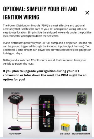
power module.jpg
 
Ferrite chokes (rings, inductors) filter induced line noise from DC wire runs. It will steady the gauges on your instrument panel if you're still running analogue. It lowers the noise floor on things with high sample rates in a noisy environment. Won't do a dang thing for AC signal wires, though.

I suppose you could just put them in everywhere, they are cheap.

I am surprised Holley hasn't engineered noise sensitivity out of their product, it usually doesn't take any more than separating power from signal when building the harness for an EFI swap.
 
Supposedly holley did work on shielding from efi on the sniper2 and a bunch of other changes/upgrades. I understand that they learned from the sniper1 and made changes to the sniper2. I'm guessing people didn't follow instructions and tried short cuts that caused holley a ton of grief. In my transmission mods I learn from things that have come up and end up making better product from those experiences.

I found these on amazon, and I think I'll order some farady tape also. I got some metalized wire loom to cover wires to prevent efi interference but there is no way to get it on the wires. I just gave up on it.

 
You might look at VFD recommendations as to how to reduce electrical noise. There are a couple of general principles similar to what has been outline by Pontiac428. One is star grounding, the use of wire shielding can help but it is very important that the shields are all grounded at a common source and only at one end. I would try the system without cable shielding, unless recommended by the manufacturer. The use of ferrite rings is often used with VFD motor cables, but there are many different kinds of ferrite that attenuate differently depending on the frequency. The wire are wrapped around the ferrite ring 3-4X, with VFD motor cables the same ring, each motor wire is wrapped in the same direction equally spaced around the ring. The type/method used depends if it is a signal or power cable, just blindly changing things can potentially make things worse.

I would start out with the manufactures recommendations, then if you still find you have issues, I consider making changes in a stepwise manner and contact the manufacturer for their recommendations. I have seen all kinds of weird EMI/RFI issues when installing VFD's, in most cases following the manufactures recommendations as to shielded wire and grounding has worked, in some cases I have had to add noise filters to either the input or output of the VFD. How and where you ground can also be a big issue.
 
Ferrite rings are cool in what they actually do and there's a fun little experiment to help understand.
What they do is remove "noise" introduced by random or stray signals that could interfere with super sensitive devices that are affected by those stray signals.
And by "signals", I mean stray electron interference.

OK, so, how do they work?
ALL electric currents create a magnetic field. So, when you want a "pure" current (call it signal), they add an electric element (the ferrite core) that will be affected by the magnetism and, basically, absorb spikes.

Yes, I do a horrible job of explaining it.

But, for the experiment. We are going to show an "eddy current" which is similar to what a ferrite core (AKA choke) does. It's not exactly the same but it works on a similar principal.

For the experiment you just need a decent sized piece of flat aluminum or copper. Brass will work if it's pure brass without any magnetic properties. Test it with a magnet. If it sticks, the experiment won't work.

Now, you also need a very strong magnet. A fridge magnet is almost useless because the more powerful the magnet, the stronger the eddy current.

To show how an eddy current forms, keep in mind that you don't have a magnetic piece of metal but if you move the magnet along the flat surface, you can feel it drag as the eddy current pulls back on the magnet.
In essence, an electrical current is formed within the metal as long as the magnet is in motion. When you stop moving the magnet, the electrical current stops and there's no eddy.

For the ferrite core, you aren't moving a magnet. The wire (electricity) is creating the magnetic field and the ferrite core absorbs it, similar to how the aluminum or copper sheet does with the moving magnet, but not so much to affect the "wanted" signal. It absorbs "noise".
 
You can get more effective filtering with ferrites by looping the wire thru more than once
Buy ferrites with a large enough hole to allow 2-3 turns
 
Ferrite rings are essentially an electrical “choke”. They are meant to cancel out emf induced in the signal/power lines.

As mentioned, the “snap on” ones are not very effective. To make an effective choke, you need to wrap the wire around the ferrite bead 3-4 times. The ferrite with wire wrap becomes a for of electromagnet and cancels out emf, for the most part.
 
Can't tell if that PDM is just a terminal block with fuses or has some filtering.

Ferrite beads can help but it is a bit of a trail and error, as pointed out by others. Really need an oscilloscope to look at the noise output to have some basis for experimentation. Ferrite beads add inductance to the wire, which creates a barrier to changes in current (smooths current flow). That can help isolate noise but if your load tends to use current erratically, too much inductance will actually increase noise on your power line. Adding capacitance after the inductance can help stabilize that.

If you're really worried about it, I'd just use a in-line noise isolator. Those use a LC circuit (inductors and capacitors) typically in a PI circuit arrangement to achieve much better isolation. Commonly used on the power rails to a car audio system but it's the same idea. Cheap version from amazon or a more pricey but probably better quality from digikey.

As others have pointed out, grounding matters.
 
Last edited:
Ferrite rings are essentially an electrical “choke”. They are meant to cancel out emf induced in the signal/power lines.

As mentioned, the “snap on” ones are not very effective. To make an effective choke, you need to wrap the wire around the ferrite bead 3-4 times. The ferrite with wire wrap becomes a for of electromagnet and cancels out emf, for the most part.
To be fair, most snap on ferrite cores are intended for radio frequencies (periodic, under 1 microsecond), and an auto ignition deals in dozens of
milliseconds spacing of few-milliseconds currents. The original post problem was a wiring harness from a previous century
being fitted to a modern ignition controller, and those ferrite rings were part of the adaptation, required probably because
of wiring pickup of extraneous signals that the modern controller was sensitive to.
 
Some additional and source of Ferrite clamp on cable types, and recommendation as to the ferrite material type. You are trying to suppress the dV/dT of the spike, depends on the origin of the noise. Ferrite beads/clamps need to be located very close to the input connection or source of the radiating device. As mentioned, 2-4 turns around the ferrite suppression material (ring or tube) greatly increases the effectiveness. As mentioned, I would install per the manufactures recommendations and evaluate if you have an issue first. Snubber circuits or reverse diodes can be used for relays and coils that can cause a reverse voltage spike when they open. By taking power from the source, the battery will absorb most of the spike, but not electrical noise.

RFI/EMI suppression - Automotive

Ferrite 31 and 43 clamp on cable
 
Back
Top