First project complete and question

dansawyer

Registered
Registered
Joined
Jun 13, 2018
Messages
442
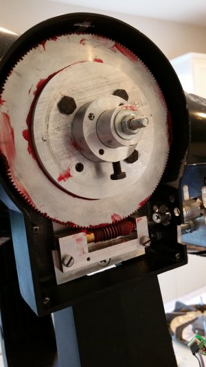
Below is a picture of my first completed project. Thank you all for your support on questions over the last year like order of machining and how to drill a hole in the center, among many.

Now the question: slightly out of view is a stepper motor driving the worm gear. The drive is attached to a telescope with a magnification of 250x. The stepper is driving the the worm / gear at a rate that tracks the earth rotation. The major rate is accurate, however the error for each rotation of the worm, about 8 minutes, shows significant error. This error shows up in photographs as roughly a sine around the major rate.

My estimate is the total error is about 90 arc seconds, i.e. + / - 45 arc seconds around the major rate. The design objective is 10 arc seconds, or a factor of 10 improvement.

Does anyone have advice on how to measure the source of that error. My first thought would be to measure error in the worm rotation on a center axis. That is the distance of the teeth from the center, in all axis.

Thought notes:
First any error in the face of the worm gear on the cage would create an undesired movement along the axis of rotation.
Second any error in the gear bearing alignment with the axis would create a rotational error, either toward the main gear or in line with the main gear axis.
How can these errors be measured?
 

Attachments

  • 20200506_175421.jpg
    20200506_175421.jpg
    1.6 MB · Views: 40
Runout of the main gear is one source of mechanical error. Another source of error is runout in the worm which would show cyclic error at a rate equal to the main gear rate divided by the gear ratio.

Personally, I would add an encoder to the stepper to verify true positioning, and have a compensation map in your software to be able to map the mechanical error you are unable to correct and add/remove steps as needed in any given position to get the positioning perfect.

The compensation map requires you to A) be able to measure error at the end actuator, and B) verify that the error is repeatable.

The motor feedback encoder would only verify the motor moved the correct distance and did not stall/lose steps.

Good mechanics will get you close, but compensation will get you near perfect.

PS: Cool Project

PS#2: Those helical couplings between your motor and the worm are kinda garbage. A bellow coupling is best, but an oldham coupling would be a cost effective option. The helical couplings add a ton of "sponginess" or lost motion when there is variable load or direction reversal. This will appear as poor positioning.

PS#3: Thought about it more, if there is runout in the main gear, then the load on the worm would increase in some positions and cause the helical coupling to spring forward more, adding to the positioning error. Adding an encoder to the worm shaft rather than the motor would compensate for any position error through the coupling.
 
Worm gears are frought with backlash, does this ever reverse, or does the weight of the telescope always cause the gear and the worm to mesh on the same side of the tooth?
 
Thought notes:
First any error in the face of the worm gear on the cage would create an undesired movement along the axis of rotation.
Second any error in the gear bearing alignment with the axis would create a rotational error, either toward the main gear or in line with the main gear axis.
How can these errors be measured?

Filar micrometer (a micrometer in an eyepiece) set first line on a star at one end of the cycle, and measure the other line difference at the other end of the cycle.
 
I tried encoders, unfortunately ones that are sensitive enough are really expensive. The accuracy of the final scope drive is less than an arc second. That implies an encoder system that can measure 1.2 million pulses per rev. The desired time range is less than a full rev of the worm. That is less that a full tooth on the main gear. I believe the main source of error is from the worm.
 
I tried encoders, unfortunately ones that are sensitive enough are really expensive. The accuracy of the final scope drive is less than an arc second. That implies an encoder system that can measure 1.2 million pulses per rev. The desired time range is less than a full rev of the worm. That is less that a full tooth on the main gear. I believe the main source of error is from the worm.

OK, save some cost and pop an encoder on the worm rather than the final drive. Does not compensate for error in the gear profile, but it does quite a lot. Final compensation can be done through software mapping.

Higher resolution encoders are available at that resolution (or better). I can help you locate one, but expect it to be several hundred dollars. IS that beyond project budget?
 
For example, here is an absolute rotary encoder. 20 bit resolution (just a bit shy of your 1.2M counts per rev), full assembly is ~$275.

 
You could also look for a more rugged version of the same sensor, albeit for a cost around $500.

1600370229512.png
 
I have a higher quality worm / gear assembly. I think I will try that. It will require machining to fit. The current gear - clutch interface is 3 inches in diameter. The new gear is 3.5. That will require machining a shim. Otherwise it should be a straight fit.
I have also heard others on scope mount thread doing things like installing ceramic bushings between the worm and the worm cage. I will measure the worm run out.
 
Back
Top