Fitting up a box to a PCB

WobblyHand

H-M Supporter - Diamond Member
H-M Lifetime Diamond Member
Joined
Dec 18, 2019
Messages
6,447
Going to print this up tonight. Hope it completes. Not sure if this belongs here or in the 3D section. Modeled this in FreeCAD. This is my ELS board sitting in an enclosure. The bottom piece of the enclosure is printing now. Need to work on the top part with the opening for the display. Lots of things to line up. A draft print seemed to be pretty good, so I was encouraged.
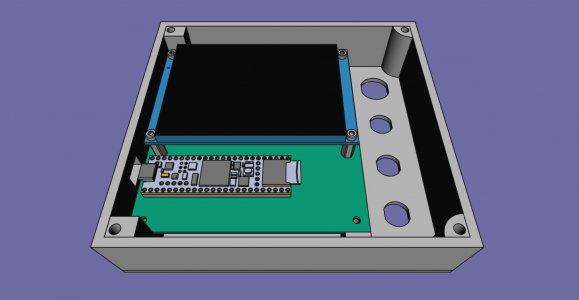
perspectiveview_ELS_PCB_enclosure bottom.jpg
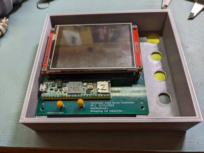
Draft printed box with real PCB. GX16 and GX12 connectors fit in the side D cutouts.
PXL_20221118_020238800.jpg
 
Almost, but not quite :(

My PCB is 98.03mm, but the printed spacing came out as 97.6mm. I could file the PCB to fit, but the cutout for the USB connector in the wall is not quite in the right spot. Needs to move almost 1.3mm. I had trouble with getting that right in the model. The cutout allows the connector through, but it's snug. This means the cutout has to be nearly exactly located relative to the PCB. I think I will open up the cutout a little more.

Well, I'm learning something. The supports for hanging cutout worked. That's neat. Good thing I ordered more filament. Been using it faster than expected. More lessons. This stuff can't be rushed! Probably will add in some pockets for some magnets to adhere this box to the headstock, while I am at it. Think I will have the magnets alternate polarity and use a thin steel plate in the box as a way to increase the holding power.

On to Rev. B! Well, after I replace a light fixture in my wife's closet.
 
Back
Top