For FDM printing, how fine a thread is practical?

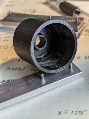
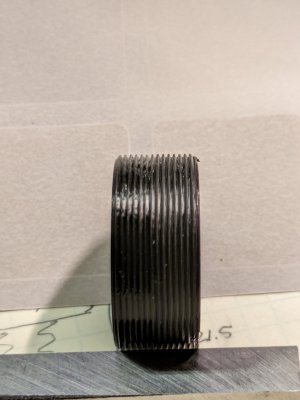
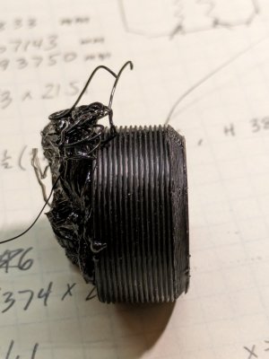
Well that print failed... Might have had something to do with going at breakneck speed though. Failed after 14mm out of 21mm. But enough to see if things looked like threads. They somewhat do. That being said I wouldn't say it's a perfect fit to my 32 TPI gauge. Pretty close though. Trying a second print, which is shorter, maybe it will succeed. If not, I'll try it at a slower speed.
PXL_20240131_011749130.jpg
 
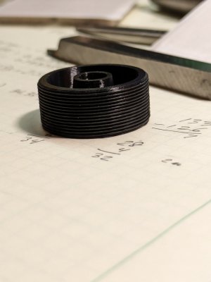
The second one came out nicer. Maybe because it had a flat base. I did put a brim on the first one though. Might of just been bad luck. There's some excess dribble from the nozzle which can accumulate, if it lands on the part, the head comes by and lifts the part off the base. I don't get it often, but I have seen it before.
PXL_20240131_015855008.jpgPXL_20240131_015938321.jpg
The first pic looks like the thread is wavy, but I have been looking for that and I don't see it on the part. The proof of the pudding is if I can make the mating part... That is next.
 
I used to construct all my threads in SolidWorks from scratch. Then I found out that the 3D models for screws and nuts in McMaster Carr are actually geometrically correct. Just import the model as a Step or Iges file and modify to meet your needs. For example, I will import a longer thread than I need and cut it to length. If McM doesn't have the head you need you can add it to the model. This shortcut has saved me a lot of time over the years.
 
FreeCAD has thread forms to use, either as taps or dies to remove metal from parts or just plain threaded rods. They are correct. It's also not very hard to create your own thread forms, with P/4 troughs and P/8 tips. The part that failed was not done very well and I need to do it over again. I'll start from a threaded rod and carve away what I need. Some approaches are more fruitful than others. I made the successful part that way, but the failed one a different way.
 
The second one came out nicer. Maybe because it had a flat base. I did put a brim on the first one though. Might of just been bad luck. There's some excess dribble from the nozzle which can accumulate, if it lands on the part, the head comes by and lifts the part off the base. I don't get it often, but I have seen it before.
View attachment 476299View attachment 476300
The first pic looks like the thread is wavy, but I have been looking for that and I don't see it on the part. The proof of the pudding is if I can make the mating part... That is next.

What size nozzle did you use here? And did you have to modify print speeds?


Sent from my iPhone using Tapatalk
 
What size nozzle did you use here? And did you have to modify print speeds?


Sent from my iPhone using Tapatalk
0.4mm nozzle. 0.1mm layers due to threads (roughly 8 layers/thread). Fast Details setting using input shaper printer profile (MK4 IS) in PrusaSlicer 2.7.1. (It was printing pretty fast!) Was getting greedy I guess, but wanted to see what would happen.

I think a die would remove a little material, but the pitch is very close. It's not bad really, although not a perfect fit to a pitch gauge, as I see some light. Need to try a short section of the female thread - don't want to wait 3 hours to find out it doesn't fit!
 
that could be why you're oozing a little, but you must have it tuned up pretty well to get those results.
 
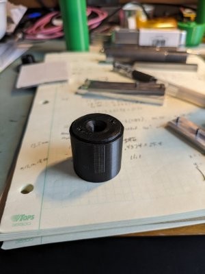
Well, printed up a female set of threads. Not perfect, but with a little bit of lube (WD40, hey, it was close by) I was able to tighten the male plug into the female threads 11mm out of the 12mm total length, before it got a bit hard to hold and torque. I simply held the 30mm high tube in my hand and use a pin spanner to screw in the plug.

I had bought a pile of 2mm diameter x 8mm long pins for a previous project and made an impromptu pin spanner for this. The plug had two 2.2mm holes in it, spaced 20mm apart. The plug went in pretty easy for the first 6mm, then added WD-40 and it threaded in some more. I should have made the pin spanner longer, it's only 3" long total, but it worked well enough to prove the point. I don't have a tap or die of this size, just gave things some clearance and put it together.
PXL_20240131_182005712.jpgPXL_20240131_182036366.jpg
I have no idea what the right thing to use for PETG thread lube, but still this is better than I had initially expected. You can see the part of the pin spanner under the printed assembly on the right side picture. Just two pins pressed into place into some 4mm thick aluminum.

There's an issue with filament uniformity and or moisture, which shows up a little in the threads. This PETG has been dried in a dryer at 55C for maybe 48 hours, (and stored in a vacuum bag with desiccant), so it should be ok, but I see varying features in the part if I look at it closely. Some is the slicer, but I think some is the Overture PETG itself. Maybe if I bought a more premium brand it would be better. For the most part the defects are tolerable.

Anyways, printing at 32 TPI has been accomplished, at least a one of. So to those that say it can't be done, well, it can be done, because I just did it. Guess I answered my own question.
 
Nice confirmation test. I’d think some silicone lube would work well.
 
Nice confirmation test. I’d think some silicone lube would work well.
I was thinking the same, but didn't have any silicone lube near by. (I have 4 oz of Super Lube Silicone Oil 5000 on my desk.) As a note, and important for my end use, was able to unscrew the threads about 30 minutes later. I'm calling this a win.

Now, if I can get some good prints of what I am trying to do. I think I will add a spare set of spanner holes in the plug, in case the first set gets damaged. The plastic can see a lot of force on those pins if the threads are not lubed. In this plug design I used 2.2mm diameter holes (which shrink,) 4mm deep. The spanner uses undersized 2mm pins that stick out 4mm from the tool.
 
Back
Top