FreeCad Assembly (A2plus V0.4.54b)

Look up "topological naming problem" for FreeCAD. This is the cause for much frustration not only in A2plus but all the tools. You can minimize this issue by creating you models a certain way. There are a bunch of YT videos on this topic. My favorites are by Adventures in creation. he has a full series on using FreeCAD.

I use A2plus exclusively and, yes, it has it's issues. I assembled my belt grinder using this with dozens and dozens of parts and had to redo it multiple times. I did find a bug that was fixed by the creator by posting it on the FreeCAD forums. Talk about service!

I tried using Assembly4, but was frustrated with creating all those LCS and rearranging the model pieces. Assembly3 has its own issues, but is closer to A2plus. I'm sticking with A2plus since it's the easiest to use not needing anything special in how the model is created.

As far as avoiding the topological naming issue, never sketch on the face of a body. Use offset sketches and datum planes. I use spreadsheets for everything now unless the model is very simple. This also helps a lot.
 
Thanks, didn't realize there were different, and doing some reading online, apparently incompatible options.

You get what you pay for ...
That's the 'advantage' of open source software, everyone can modify it! :rolleyes:
 
That's the 'advantage' of open source software, everyone can modify it! :rolleyes:
Somewhere I heard the quote "Given enough monkeys and enough typewriters, you will eventually get Shakespeare".

I am, in general, a big fan of open source software, having started with Unix Source Code License (academic) in the 80's, building early versions of GCC, and then going into Linux, using GNUradio (software defined radio), and etc. I've also seen some true disasters, TI put out a developer chain for an image processing CPU that was nearly impossible to replicate the build much less enhance. Poor internet connectivity is my current bane.
 
Last edited:
The render on the wheel was by choosing selecting the wheel, and going for "Appearance" options.
If made with "Part", you end up with the "Set Colors" tool, on selected faces.
I will attempt to post a simple example here, given you cant play with the YT video.
Given that much of a hint I can probably figure it out. Hadn't really been worried about it, I'm the only one looking at my design so as long as I can understand the rendering I'm happy, just a passing curiousity.
 
As far as avoiding the topological naming issue, never sketch on the face of a body. Use offset sketches and datum planes. I use spreadsheets for everything now unless the model is very simple. This also helps a lot.
Ah ha, that is probably my issue. Thanks.
 
Given the simple stuff I want to do, I find I can get stalled when I get deeper into something new .
Then again, the finite element stress analysis, for example, just happened easily.
Using the simple example of a simple table with a weight on it, I was surprised that in about 10 minutes, I had the whole bendy legs display going.

One thing I found useful was how to import a phone image, and have it display while making a sketch over it. Easy to trace out profiles, or make outlines forced to be straight. Best is to be able to mark two points on the photo, and assign a real dimension as measured, and then have the sketch scale to make all its dimensions agree.

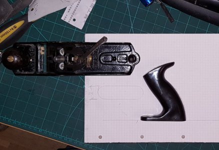
Example: For making a replacement hand plane handle, in alternate horizontal 5mm thick slices of oak, and mahogany, there the need was to get a 1:1 profile on a piece of paper to stick onto the side of the set of glued together blocks, for the first cut-out. I took a photo of a cheapo eBay plastic handle.
Here is how it went..
1 Stanley Bailey No4.jpg . Stanley Handle (not full size).png

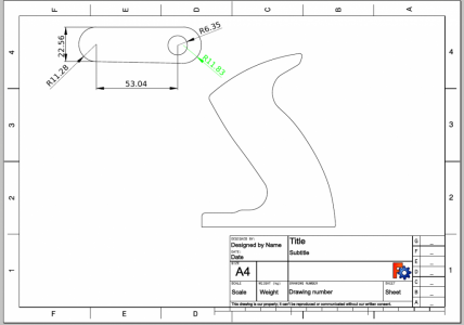
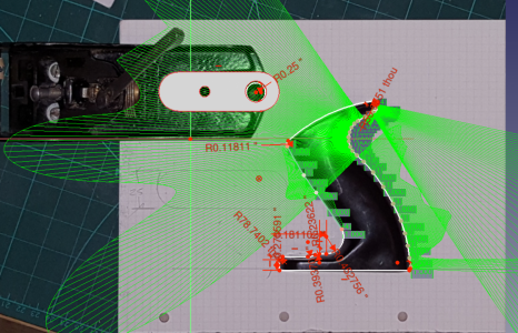
Forgive the mad display of Bezier splines curvatures and colours. This was before I had customized things. All I was doing was plonking down points along the profile, using more points closer together at the more highly curved places, but otherwise, just various arcs and lines. I gave the meeting points tangential constraints, and moved them until they followed. The arc's radii then settled on obvious conventional values. The scaling came from the 53.04mm, which was an obvious attempt at 2 inches

Stanley Handle Splines.png

This whole thing was done in a bit of a hurry. The angle measure tool allowed me to establish the angle of the stud fixing rod through the handle was 60°, and the pictures let me see exactly how it would be drilled, and where it would exit. It was actually easier to pilot drill the slices before doing the glue job.

This block set, and drawing, along with 3 vintage various size Stanley planes for restoration, was given to my daughter's significant other as a Christmas present. He, being a woodworker to cabinet grade, would have no problem making the finished handle. I will post a picture when/if he sends one.

Its just as easy to take a photo of a gear, or lathe assembly, whatever, then measure for real just one dimension, and end up with an accurate model.
 

Attachments

  • Handle Shapes Template.pdf
    221.5 KB · Views: 3
Last edited:
So I still get the feeling that FreeCad is a nightmare. Graham you almost convince me to dive back in, and Randal your model looks better in freecad than I could get to. But having used sketchup and watched many fusion 360, it's still a nightmare tool. Non-intuitive, ugly in its flaws.

I may give it one more go, but I still don't feel the love... I found it totally frustrating. I used Autocad back in the late 80s or early 90s. A friend had a licensed version, and brought his computer over and gave it to me to play with for a while.. it was tough going, but I got further, that with a super low res screen.. not like we have today..

Graham and Devils4ever seems like you are all in on it. My son struggles with it, and he has never struggled with anything computer wise. He does models for 3d prints; but he says it's so hard to come up with complex models with this tool. He was hoping to go to the maker version of Solidworks because he doesn't want his models on line like Fusion, but Solidworks went that way too for the makers.. So freecad it is.
 
It is all too easy to see all the tools, and get in a knot before realizing some basic concepts. The history of the way it was created, and the open source scripting from Python with the insistence that it never become incompatible with it's later versions, meant that the more intuitive interface features came later, and are continually being added almost every day.

Try viewing this example. If you still find it extremely difficult, then describe what, in your view, is truly awful! Most who have complained in the Forums, over time, only had to be shown an easy way. For the rest, the usual response was "Yep - that bit sucks, and there are several guys in there doing something about it". Often, the folk who get frustrated, send in suggestions, or code of their own.

FreeCAD Practice Part |JOKO ENGINEERING|

Now, the 3D printing feature, and G-Code output, is pretty much tested.
(BTW - I don't use the blue gradient background in my default configuration)
 
Last edited:
Back
Top