Funny Snafu With My Pm-1340gt

You folks are headed off in the wrong direction about looking for a metric equivalent.
It is a rack and pinion system with a gear reduction in the carriage.
The travel distance will be a function of the pitch diameter of the pinion, so it will be something irrational provided the radius is rational.
One could engineer it so that the gear reduction will work out to an approximation of some whole number. It would be a tricky puzzle to work out the math for the proper gear reduction and pinion size to provide some reasonable distance per turn given a set of size constraints for the gears and shafts. 0.58" is close enough to 0.50 that that could be used as a target for the solution. Probably easiest to just solve it numerically, rather than find it with calculus.
 
Not really that tough of an equation to solve. This isn't rocket science.

M7 G0709 goes from a 14T:60T then to a 13T to drive the rack. The diameter and # of teeth (13T) is what is the driving part of the equation for distance travel per revolution. An that is not that tricky. One turn of the hand wheel drives the 13T drive gear 1/4.285 of a rotation. 0.580" per revolution of the hand wheel means that every revolution of the drive gear travels 2.486" along the carriage. That makes that drive gear 0.791" in diameter (20.09mm...hmm...close), and the pitch of the rack has to be 5.23 TPI.

No quadratic equations required. Didn't even need to pull out a scientific calculator. Although I might need a pencil and paper to determine the profile of the gear.

To get 0.500" per revolution, I would need a drive gear that was 0.682" in diameter, and a rack that was 6.068 TPI. I probably wouldn't do that, but would change my first reduction to get a beefier diameter drive gear.

The strange thing is that NO attempt seems to be made to achieve a "countable" value with EITHER imperial or metric values.

I just call this sloppy engineering personally. It would be no harder or more expensive to cut the gears to get a clean 0.500" that an offbeat 0.580". You can't tell me that a rack with 5.23 TPI is an off the shelf item. And since other lathes manage to do it...
 
Last edited:
hmmmm
Not an expert on gears, but I do know that pitch Diameter = Number of teeth/Diametrical Pitch, and there are standard DP's. This means that unless you plan to use custom ground gear cutters, pitch diameter is constrained to set values depending on the DP and the number of teeth. This is why outfits like Boston Gear can publish gear templates that you can lay any standard random gear on top of to find the PA and DP. Likewise, racks have a fixed number of teeth per inch for a given DP and PA - and this TPI will almost always be some weird irrational number (because pi is used in the calculation). For a manufacturer, the cost difference between custom tooling and standard off the shelf tooling can be very substantial, not to mention the potential difficulties in sourcing.

I'm not an engineer, I just picked up a BS in math for fun when I was doing my real major, so I am probably showing some true ignorance here about tool manufacturing.
I admit up front that I have limited experience with gearing, and I know very little about actual manufacturing methods. I have no doubt that CNC machined precision gears can be just about anything a person wants. But I am pretty sure that this is just a standard grade 3 or 5 rack and pinion and just made with some mass manufacturing process. This means standard tooling, on old fashioned automated machines.
So:
13teeth/.791diameter = 16.4349 diametrical pitch
not exactly a standard DP...
16 is a standard DP though
13/16 = .8125 diameter
.8125*pi = 2.552" of travel per revolution of the pinion.
So for 1/2" travel for 1 rev of the handwheel we need calculate a gear ratio by 2.552x = .5 -> x = .19588.
39/200 = .195. .195*2.225 = .4976 (0.0024" error)
Pretty sure you won't get a 200 tooth gear in that apron though...
10/51 = .1961, but .1961*2.552 = .4907" (big error) and a 10 tooth wheel is awkward...
Seems this might not be so simple after all.
I also neglected to calculate transmission losses because I do not know how it is done, or if it is appropriate in this situation.
No idea if a 16DP is even appropriate for this situation. I know 16 and 20 are commonly used in linear motion though, so probably best to stick with one of those.
This is even assuming the whole thing even uses the DP system. I know there are other systems for designing this sort of thing. Dunno if they are better or worse, or anything about the cost of these systems.

I figure I already paid $6K for this lathe. I would not pay another $1k just so the hand wheel came out to 1/2" per revolution.
I will agree up to a point that there might be some lazy engineering here. It would take me less than an hour to write up some code that could find all possible solutions given a set of DP's and diameter constraints. It is entirely possible this was done and that no solution exists that does not entail either custom tooling or large error, and they just opted for a solution that had the least error and came out to some random 1/100" ( in this case 0.58).
 
Sure seems like Matt would send you a replacement wheel. Like tmarks11 mentioned on the G0709, odd 0.580 per turn. Seems like that's a function of the number of teeth on the longitudinal hand wheel and the rack.

Bruce
 
16 is a standard DP though
13/16 = .8125 diameter
.8125*pi = 2.552" of travel per revolution of the pinion.
So I just double checked my G0709.

Not 0.580 per revolution. An even more convenient value... 0.565. Put a test indicator on it to confirm that the hand wheel marking was accurate... and it was.

Frequently cheaper chinese machines "achieve" imperial values by marking the hand wheels as if they are imperial when they are actually metric... and you find that four turns of the 0.250"/rev hand wheel gives you 1.016" instead of the 1.000" you were expecting... since it is actually a 25mm.rev hand wheel.

Using your math, my gear ratios doen't work out to DP16 (0.595 per hand wheel turn) or DP17 (0.560 per hand wheel turn). So we are obviously looking at a different profile drive gear.

Anybody have a parts list for the PM1340GT? I would be interested in what gear ratios they have in the apron for the hand wheel.
 
A good machinist wouldn't pay no nevermind to those numbers and lines. It could be worse....instead of arabic numerals, it could be chinese chicken scratchin'!:grin:
 
The problem is easily resolved by removing the dial completely. My 50+ year old Atlas and 2 year old Grizzly don't have a dial on the carriage crank so no issues.
 
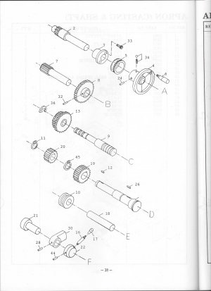
Here is the page from the manual. The shaft A is the hand wheel, and B is the pinion drive.
The parts list just calls them "GEARS." for instance, part #8 is
8 | 3310 | GEAR
I count 34 teeth on the picture, no idea if that is what the gear actually has.
The gear that drives it has 5 visible teeth, so if the image is correct, that is a 10 tooth gear.
The teeth on the pinion are not really countable in the pic, but it appears to have between 13 and 18 teeth.
The pinion is buried far enough into the saddle I would have to put my head in the chip pan to get a good look at it.
The center distance between shaft A and B is about 2.3" by eyeball with a caliper.

given an approximate center distance of 2.3, we can approximate the number of teeth for 2 equal sized gears by 20DP*2.3 = 46 teeth, or 16DP*2.3 = 36.8
So I would take as a given that there is between 70 and 100 teeth total on both gears in the reduction depending on the DP. This is also consistent with the 60:14 ratio on G0709 which has a very similar looking apron.
If we assume 14 and 60 teeth and a 16DP
center distance = (60 + 14)/(2*16) = 2.3125" which sounds pretty good to me, and is nicely consistent with tmarks' calculation.
The circular pitch is pi/diametrical pitch = pi/16 = .1964 which is fairly close to the difference between the .565 of the G0709 and the .58 of the PM1340GT, the error is probably attributable to lash. Sounds like the PM just has one more tooth than the Grizzly.

Not sure what any of this actually means though, but math is always fun :)
Scan0001.jpg
 
I sent the photo to Matt... he was really surprised by it as well stating he has never seen a mistake like that before. He is sending a new one... and this one will find a place among my collection of oddball things from other hobbies and life's experiences.
 
Looking at the OP dial, there's another five ticks between 0.560" and 0.000". I'm guessing that it's really 0.600" per turn, with 0.040" between major ticks and 0.080" between numbered ones. Then you've got 15 major ticks going around, of which 8 are numbered.

The weird thing is dividing the major ticks into 5 minor ticks, each being 0.008", for a total of 75 ticks. If there were 4 minor ticks per major, each one would be a nice even 0.01". Instead, the minor ticks go 0.480", 0.488", 0.492", 0.496", etc. 4 minor ticks per major would give you 60 ticks total, a nice even number for a dividing head.
 
Back
Top