G0602 tailstock driving me nuts

How long have you owned it?
My wife hadn't left me yet. She's been gone going on three years. Call it three years? Going on four? The deal I've been whining about in this thread is definitely annoying, but it isn't causing me any quality of work problems. (No, my sheer incompetence is causing me quality of work problems!) Grizzly is a name brand, but realistically, it's the Asian import that has a manual written in English, and possibly higher than average quality control. It ain't South Bend. (Irony intentional.)
No idea how to approach the roughness problem. Just a caution ... Most cam locks I've had experience with have had pretty limited travel. I don't know if it's practical to build one with enough range to handle a surface as rough as you describe yours to be. If it has too much range, it may not have the leverage needed to hold securely. Best wishes solving your dilemma.
I keep looking at the cam lock on my dusty, little-used wood lathe, and I just can't see it. As annoying as it is to use a wrench, it's not uncommon for me to start pushing the tailstock back with the tailstock quill, and having to go snug it down. A cam lock just wouldn't have enough grab, even if I improved the roughness of the casting.
 
Expanding on what Mitch suggested, you could epoxy a couple of scrap files to the ledges on the clamp plate then gently slide the tailstock with light clamping pressure to remove the high spots. Use heat to remove the files from the clamp plate later. Switch to sandpaper for a smoother finish. Sounds like you might want to replace the clamp plate anyway. Not an ideal solution but it might work well enough.
 
I looked at the underside of my 602 and the tailstock clamp rides on a milled surface. Cast iron pieces are usually cast in sand molds and finishes would not be suitable for a bearing surface.

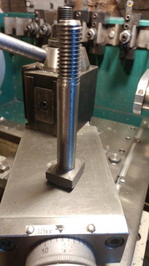
After examining the clamping block, I decided that I needed a square head bolt to provide more contact area. I found an old 5/8" square head bolt formerly from a utility pole. The head was 15/16" and the clamp slot is nominally 3/4", actually .793" so I ground the head down to .785 across one side and reduced the other side to .895" so that I could insert it into the 1.19 bore of my 3 jaw chuck. I cut the shank to 3.5" and turned enough of the shank to .500" to fit my chuck jaws. Then I reversed the bolt with the head inside my chuck and I turned the remainder to .500". Then I single point threaded 1-1/2" of the shank for 1/2-13 tpi.
Tailstock Bolt .JPG

The bolt provides a much crisper clamping due to increased surface area.

The ironical thing is later this afternoon, I happened to pick up a bolt salvaged from a defunct HF caster. https://www.harborfreight.com/6-in-rubber-swivel-caster-61844.html. It was a nominal 1/2" in diameter but the threads weren't 13 or 20 tpi. At the time I salvaged it, I assumed that it was a metric thread. Checking it with my thread pitch gage, it wasn't metric. Actually, it was a perfect fit for 12 tpi! A close visual examination showed the threads were 55º. A 1/2 -12 tpi Whitworth bolt and 3-1/2" long to boot. The bolt head measured out at .799" across the flats, about .010" too large to fit the clamp slot but that is easily remedied. Who'd have thunk?
 
I got the parts, cut one end off the lead screw, machined the square nut to fit, and put it all together.

In the plus column, the clamping action on that acme screw is really nice, and it takes about half as much wrenching to move the tailstock around. It's definitely an even better step in the right direction, and as a bonus, using the same wrench as my tool post means one less wrench to juggle.

In the minus column, it was still only an incremental improvement. If I start with the tailstock snug at the far right, back it off half a turn, and slide it, it doesn't go far before thunking to a halt. Back off more, keep sliding. Same song and dance. Fewer turns of the wrench for sure, but still enough turns to be really annoying.

While watching a random Youtube video, I got an additional idea. Somebody made a casual, passing reference to putting a spring in this setup. I have plenty of clamping oomph to overcome a spring without it being bothersome. I'm going to conduct an experiment to see if throwing a spring in here will improve anything. Easy enough to try.
 
I had a similar problem with the G4000 and I put a spring between the clamp and the tailstock. It did help a little but I still had binding.
 
I modified the 1/2" Whitworth bolt to fit and it provides slightly more range. It has a 15/16" hex head so there is only slightly more bearing surface than the OEM bolt. Additionally, the nut is also 15/16" which means a additional larger wrench. For those reasons, I decided to stay with my solution in post #13 above.

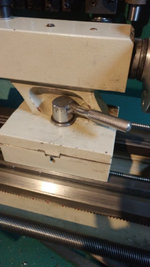
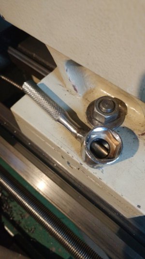
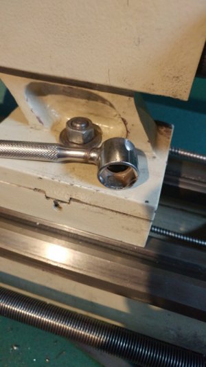
I decided to make a dedicated wrench for the tailstock clamp. It would remain on the nut removing the hunt for it when I needed to clamp the tailstock and would always be in the correct position for tightening. For starting materials, I used a 3/4" 6 pt. socket from a cheapie 3/8" drive set that I had bought years ago as an emergency set for my truck. For the handle, I used a broken 1/4" ratchet. I removed about .150" from the top face of the socket and drilled socket slightly deeper to accommodate the protruding bolt threads. Then I milled a .375"w x .375"d. slot in the top of the socket. Next, I welded the ratchet handle in the socket and cleaned up the welds. Here is the result.
Tailstock Wrench 1.JPG Tailstock Wrench 2.JPG Tailstock Wrench 3.JPG

Just over 120º of rotation is required to go from full lock to full travel on the ways. The wrench has about 170º of motion. The handle is short enough that it doesn't interfere with the tailstock crank and it is happy to sit in place while using the lathe. If needed to be removed for ome reason , it wrench slips on and off easily.
 
I decided to make a dedicated wrench for the tailstock clamp.
I totally love the idea. Sadly, even replacing the bolt with a 1/2-10 acme screw, and putting a spring on it didn't get my machine to a point where 120º would be a useful amount of rotation. I either need to go even more ridiculous on the travel or live with it until I can alter the underside of the ways. If I could think of an efficient, secure, and non-destructive way of just adding meat to the underside of the ways, this setup I have now would be the cat's meow. It's just that the difference between the "parking" position at the far right and the "useful" range toward the middle is so insanely extreme on my particular lathe. Based on what people have commented, I have to conclude that my particular example is a lot more crappy than is typical. Of course it is. I mean, that's my luck, right? I marry a woman, serve her faithfully for 24 years, and she cheats on my trusting ass, even though I thought she was a unicorn. Oops, I'm having a pity party again.
 
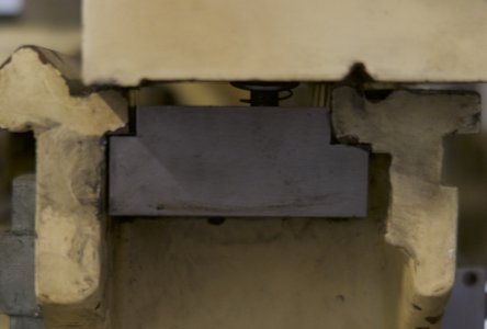
Also, take a look at the step on the clamping plate. My G602 had jagged edges and the step "machined" into the plate wasn't straight. You might be able to make some improvements there. I like Grizzly, but I have gotten some unusable pieces/parts from them. Kinda scary the QC that happens somewhere along it's long travels. Seems like you could just lift one side of the lathe (tailstock side) and clean up the underside of the ways, assuming it's something that can be cleaned up.
 
I totally love the idea. Sadly, even replacing the bolt with a 1/2-10 acme screw, and putting a spring on it didn't get my machine to a point where 120º would be a useful amount of rotation. I either need to go even more ridiculous on the travel or live with it until I can alter the underside of the ways. If I could think of an efficient, secure, and non-destructive way of just adding meat to the underside of the ways, this setup I have now would be the cat's meow. It's just that the difference between the "parking" position at the far right and the "useful" range toward the middle is so insanely extreme on my particular lathe. Based on what people have commented, I have to conclude that my particular example is a lot more crappy than is typical. Of course it is. I mean, that's my luck, right? I marry a woman, serve her faithfully for 24 years, and she cheats on my trusting ass, even though I thought she was a unicorn. Oops, I'm having a pity party again.

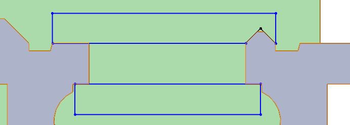
Have you measured the actual thickness of the bed? It can be measured with a micrometer. (the drawing is for reference only and the dimensions are not to be taken as accurate) As I had stated, I measured approximately a .015" difference along the ways on my 602.
602 Issues.JPG

The best way to eliminate the problem would be to tear down the lathe and recut the bottom surface with a T slot cutter. It would require something like a 1-1/2" cutter. Not cheap. You would also have to mount the bed on the mill and shim it up to make the upper flat surfaces parallel to the mill table.

An in situ solution might be to scrape the bottom surface with a custom scraper. I would envision a tool with a top plate that matched the geometry of the bottom of the tailstock and a bottom plate with two HHS or carbide cutters. The distance between the plates would be controlled with opposing screws like a machinist's clamp. The scraper could be coupled with the cross slide to allow for power scraping.
602 Issues.1.JPG

The third option is to just live with it.

I can relate to your marital woes. My ex decided to start cheating after 22 years of marriage. It took some time to finally get her out of my life but I have since remarried and prospered now that the mill stone was removed from aroud my neck. Going on 22 years with the second wife now.
 
I have the Jet version of this lathe and it had the same problem. The casting for the lock was horrendous, and it would always bind. It wasn't flat and it didn't match the underside profile. Still, I found that much of my problem was paint on the sides and underside, but there were some rough spots that I took care of with a file in an improvised jig.
The original lock would bind due to the offset that you describe, and a spring didn't cut it. I machined a much larger, heaver one that kept it guided so it would not rotate and bind, and machined the steps to match the offset. The bottom of the tailstock also was far from flat or matching the vee, but I brought it in by filing and scraping. Now I can adjust it to <90 degree turn of the nut to lock it, and it never slides when locked.
Vast improvement in enjoyment operating this lathe.
tailstock clamp.jpg
 
Back
Top