Gear drawings for a 3 d printer

Ron Frasier

Registered
Registered
Joined
Apr 29, 2020
Messages
12
Doles anyone have some gear drawings for 16 dp,14.5pa with 5/8 bore I would like to try some printed gears for my 9 JR
Like a 52 t or80 t,64t.
 
There's a gear tool in FreeCad. Type in the parameters and poof--it appears.


Here's a step-by-step description on creating the gear above for reference. Since FreeCAD has a steep learning curve, I wish I had this when I was learning.

Creating a 52 Tooth, 16 DP, 14.5 PA Involute Gear with 5/8" Bore
----------------------------------------------------------------
1. Start FreeCAD. See below to set preferences if FreeCad was never used
before.
2. Close Start Page (if desired) by clicking on "X" on tab.
3. Click on "Create a new empty document" icon (top-left) or type CTRL-N.
4. Select "Part Design" workbench from menu (top-center).
5. Click on "Create Body" in Combo View->Tasks window (top-left).
6. Click on "Create Sketch" in Combo View->Tasks->Start Body (top-left).
7. Select "XY_Plane (Base plane)" in Combo View->Tasks->Select Feature
(top-left).
8. Click "OK".
9. Create the bore of the gear by selecting the "Create a circle in the
sketcher" (top-center). Icon looks like a circle with 2 red dots.
10. Move mouse to center of drawing area and click on center red dot (should
turn yellow). Make sure the dot turns yellow. Otherwise, the circle will
not be centered in the XY plane. Move mouse outwards and click again to
create the circle.
11. Hit the ESC key to exit circle drawing mode.
12. To set the diameter of the circle, click the little arrow next to
"Constrain an arc or a circle" (red circle with red line at about 1
o'clock) icon select "Constrain diameter". Click on the circle just
created and enter "5/8"" for diameter.
13. Hit "ESC" to exit circle constrain diameter mode.
14. Click on "Close" in the Combo View->Tasks (top-left) window.
15. Click on the "Model" tab in Combo View to see the Sketch just created.
16. Click on "Part Design->Involute Gear..." (top-left) to bring up gear
tool.
17. Enter: Number of teeth: 52, Module: 1/16", Pressure angle: 14.5 deg.
Leave High precision: True and External gear: True. Note that Module
is the inverse of DP. Make sure you use inches.
18. Click "OK".
19. In Combo View->Model click on "InvoluteGear" (top-left).
20. Click on "Pad a selected sketch" icon (top-left). Icon looks like a box
raised above a gray perimeter.
21. Enter the desired thickness of the gear in "Length". I used 1/2". Leave
"Type" as Dimension. Leave others as defaults. Click OK.
22. The gear is 3D now but it cannot be seen unless you click on the
"Isometeric" view from the top-right small box in the drawing area. Or,
use the mouse to rotate the view as described below.
23. Rotate the gear to see the bottom. You should see a circle on the gear
that is to become the bore. Select "Combo View->Model->Unnamed->Body->
Sketch" (top-left). Or, select the circle on gear itself.
24. Click on "Create a pocket with the selected sketch" icon (top-left).
Icon looks like a blue rectangle with a red center.
25. In the Combo View->Tasks window, select Type "Through all". Click on
the "Reversed" checkbox. Click "OK".
26. Save the file in "File->Save As...". Enter a name under "File Name:".
27. At this point, the model is complete. I would use the "Path" workbench
to create a G-code file for my milling machine. Since you are using a 3D
printer, you would need to export the model to a slicer. I have no
experience in this.

General Info
------------
1. In the main drawing window, you can use the mouse to pan, zoom, rotate
the drawing as follows:
a. holding the center mouse button will allow you to pan.
b. moving the center mouse wheel will zoom in and zoom out.
c. hold the "Shift" key down, then hold the right mouse key down and
move the mouse to rotate the 3D view.

Preferences
-----------
1. Select "Edit->Preferences..." (top-left).
2. Under "Units" tab, select "US customary (in/lb)".
3. Select 4 for "Number of decimals".
4. Click "OK".
 
Thanks for all the work I have tried neuromas times and i just cant get it done i get stuck at number 19 and i don't know why .
I have a grandson who might be able to help me . thankls for all your help.
 
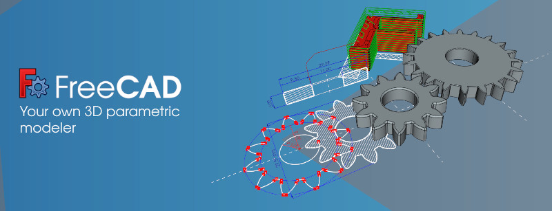
Hey, this works. Thanks devils4ever for those great instructions. It took me several hours to work through this. Freecad as included in the bionic beaver Ubuntu repository is broken. If you type the error message into a google search, one of the first few hits says that this is a known bug and gives the correct solution, which is to enable the ppa archive to get the recent stable build. Then, freecad comes up in a strange mode and requires a lot of fiddling to get to the workbench. Then, dead in the water. Searching on the error message on google again leads to a post to run the tutorial of that funny slanted part. If you do this, it clears some junk mode that prevents working on the part body, and mysteriously all the steps work. Oh, not the dimensions. If you type in 1/16, it doesn't know what you are talking about, but 0.0625" works fine. Also, the backspace key doesn't work in the text selection boxes, and you have to select with the mouse and overwrite. Also, something is wrong with the mouse buttons, but fiddling works. I am attaching the file created. This is pretty neat, but as someone who has dabbled in software, this stuff is pretty sickening.

Oops, cannot attach file. Unsupported type. Well, it did eventually work, but you'll have to take my word for it.
 
Ron: Sorry you couldn't get it to work. I've been playing and struggling with FreeCAD for some months now and I still get frustrated at times. I didn't even know there was a gear tool until about a week ago. Drafting software, especially 3D, is hard to learn. It took me a while to get used to this "parametric" drafting software. If you want, I can try and create a video of the steps.

ericc: Glad it worked for you. Wow, the install was bad? That would be challenging to say to least to figure out.

I started out using Fusion360 since FreeCAD seemed a littler harder to use and a little more limited. I switched when I perceived that Fusion360 was headed towards removing the free version for hobbyists. After using FreeCAD more, I realized they are both hard to learn and use and that FreeCAD is not as limited as I thought. I still have to look on youtube for videos on doing something specific. I found that google and youtube are your friends in learning FreeCAD since the documentation is lacking or obsolete. There's a lot of documentation out there that doesn't work because it's for older versions.
 
Back
Top