Guy I met made his ac drive totally variable using a "Bridge"

Buffalo Bob

Active User
Registered
Joined
Sep 28, 2013
Messages
40
Long time ago I visited the workshop of an electrical engineer. He had every machine you could think of. Metalworking, wood etc all layed out in his basement. He was selling something and I was checking it out.

His workbench though was for electronics. He had capacitors? I think, the round tube jobbos with wires at each end. He was building what looked like an accordian of these things all wired together. He called it a Bridge. All his machines were equipped with them. Variable speed.

He had hundreds of those parts segregated in bins. Middle container was whatever the standard part was called. Like it was a "100" that was commonly used in all electronics. However he knew that the actual output was subject to manufacturing variability. He measured somehow each "100" component and the +/- range was maybe -5 to +10 of the stated spec.

And by wiring a group from -5 through the highest +10 maybe, that was all he needed to make all motors VS.

This was a house in Chicago but I don't recall if the motors were single phase 120v or three phase or whatever. My understanding was his Bridge was the only mod needed. He proceeded to power up his table saw through slow speeds to full on. Scared me. It was whistling.

What can you tell me about that technology. He made these to sell to other engineers so it was common in the early '70s. I've met some interesting people in my life and he was special. If this rings a bell or is common technology let me know?

Merry Christmas to you good folks... :)
Bob
 
If the wires were coming out both ends, and they were more or less brown in color with colored bands on them, they were resistors, which would make much more sense for a variable speed control. I do not know of a way that capacitors could be used as the primary component in a speed control. One of our more electrically minded individuals would have better information than I can give.
 
Re: Guy I met made his ac drive totally variable using a "Bridge"

If the wires were coming out both ends, and they were more or less brown in color with colored bands on them, they were resistors, which would make much more sense for a variable speed control. I do not know of a way that capacitors could be used as the primary component in a speed control. One of our more electrically minded individuals would have better information than I can give.

Wermie I think you are correct. Thanks...
I Googled it but no idea what it is. Would be a neat project if I had references or build plans. All the electrical engineers I know have jobs so need to poke around for more info.
https://www.google.com/search?q=cap...ge&rls=org.mozilla:en-US:official&safe=active

BB

- - - Updated - - -

A Diode Bridge http://en.wikipedia.org/wiki/Diode_bridge
can turn "single phase ac into dc current" . Cool.. I keep researching.
Bob

Jump to: navigation, search

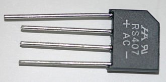
330px-Diode_bridge_1000vx4a.jpg http://en.wikipedia.org/wiki/File:Diode_bridge_1000vx4a.jpg

Detail of a diode bridge, rated at 1000 Volts x 4 Amperes


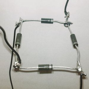
330px-Hand_made_diode_bridge.jpg
A hand made diode bridge. The thick silver bar on the diodes indicates the cathode side of the diode.


A diode bridge is an arrangement of four (or more) diodes in a bridge circuit configuration that provides the same polarity of output for either polarity of input.

When used in its most common application, for conversion of an alternating current (AC) input into a direct current (DC) output,[SUP][1][/SUP] it is known as a bridge rectifier. A bridge rectifier provides full-wave rectification from a two-wire AC input, resulting in lower cost and weight as compared to a rectifier with a 3-wire input from a transformer with a center-tapped secondary winding.[SUP][2][/SUP]

- - - Updated - - -

On a roll here. YouTube has some DIY instructions.
[video]https://www.youtube.com/results?search_query=how+to+make+a+bridge+rectifie r%3F&sm=4[/video]

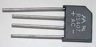
330px-Diode_bridge_1000vx4a.jpg

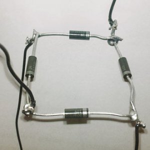
330px-Hand_made_diode_bridge.jpg
 
Last edited by a moderator:
Thinking it's not a rectifier bridge. Typical motors like you mentioned probably found on the table saw would not be DC. You cannot run an AC motor on DC, which is roughly what comes out of a rectifier. I say roughly because it is not true, pure DC.

If what you were seeing is a set of large wattage resistors, you can limit the current (AC or DC) sent through a circuit but that is not the proper way to control motor speed. There must be something more to what you saw.
 
Sounds like he built a PWM generator and is using it to control the motor speed by the duty cycle. That's how quite a few are done and it works exceptionally well in most instances...

Bob
 
Wouldn't PWM lose a lot of torque at lower speeds? Don't know a thing about this application, but I know what PWM is, and I'm curious how that would work for this.
Aaaannnnd, knowing me, I guess I should mention that I "know" PWM as Pulse Width Modulation. Maybe this is something different. :)
 
Last edited:
A PWM If that is what you mean is a Pulse Width Modulator. This is a device that turns on and off for each cycle and limits the duty cycle power. In other words, normal AC has 60 cycles or Hertz. When looking at this on a scope, it is a sine wave that crosses the 0 point 60 times a second. The power curve is full wave. If you limit the pulse or hertz width to have the wave form, the power is limited so the motor slows down. I think that I remember that an single phase AC motor will heat up and not run efficiently. It's been too long out of school for me.
 
He probably used an H-Bridge. Reversible and able to use Pulse Width Modulation for speed control.

An H-Bridge can be constructed with 4 power transistors driving an motor. He may, be using a micro controller to drive the h-Bridge alternating mode. One could rectify the ac line using a bridge rectifier to produce AC and drive the motor via an h-bridge creating an AC of varying frequency.

I agree that using an H bridge and PWM would be a way to do this today, however - the time frame mentioned (1970's) would mean that it would take a lot more to do t that way back then. I worked in electronics for 38 years after graduating from Vocational School in 1975. There were a few IC's that would do PWM for the then new switching power supplies, and even the old 555 timer could be set up to do that. The H bridge would have to have been built using multiple transistors, since the power transistors available wouldn't handle much current, especially at high voltage, and a pretty large heat sink would have been needed. Triacs and SCR's were really getting popular for motor control back then. I've even seen the old triac light dimmer circuit used to control motor speed - and considering the time frame, I would guess that he was using some sort of triac circuit - they were cheap and easy to build, and would handle quite a bit of power using only a handful of parts.

The components mentioned sound like capacitors, and back then, the way to measure the value of these (as was mentioned) would have been to use an LCR Bridge to measure the value. I'm not sure the capacitors would have been a part of the speed control circuit - maybe just something else he was playing with? Just my $.02 worth.
 
Back
Top