- Joined
- Oct 28, 2020
- Messages
- 532
Hey Girls and Guys
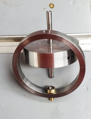
Today in my shop I continued to develop a prototype for a Gyroscope Kit I am working on. Today specifically was the upper bearing housing.
The "wheel" is 3" diameter cast iron (prototype shown is steel) and the frame is from 3" heavy wall pipe. The axle will ride on deep groove ball bearings.
The intent is to create a skookum Gyroscope that will stay upright for a good long while.

Lots of cool items over at my store.

Today in my shop I continued to develop a prototype for a Gyroscope Kit I am working on. Today specifically was the upper bearing housing.
The "wheel" is 3" diameter cast iron (prototype shown is steel) and the frame is from 3" heavy wall pipe. The axle will ride on deep groove ball bearings.
The intent is to create a skookum Gyroscope that will stay upright for a good long while.

Lots of cool items over at my store.

Kits For The Home Shop Machinist/Tinkerer
Kits for the home shop machinist. Hi my name is Doug Gray thanks for stopping by my shop. I'm am the sole proprietor of D. Gray Drafting and Design. I lovingly create all the kits you see here in my shop. Everything from creating the drawing to assembling all the materials and packaging them up...
d-gray-drafting-and-design.myshopify.com

