Hardwiring DRO to lathe electrical cabinet

boostin53

Registered
Registered
Joined
Sep 11, 2015
Messages
293
Is it common practice to do such a thing? I just recently installed a DRO on my Grizzly G4003G, and I didn't have a 110v plug near the lathe. So with the help of my father, he explained how the electrical system in my lathe worked and how the 220v coming in gets split and what not.

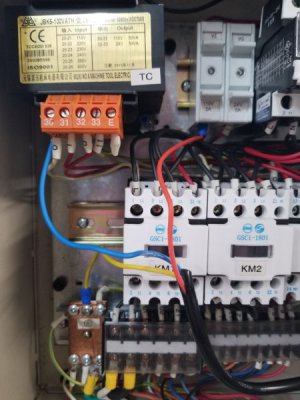
It was fairly simple to wire the DRO monitor to a clean, protected circuit inside the electrical box. Now I don't have any cords plugging into any unnecessary outlets. If anybody would like to see the wiring, I'll gladly share it.
 
Did you have to run a neutral wire? Most 220v machines don't require one. Just curious as to how you handled it.
 
Did you have to run a neutral wire? Most 220v machines don't require one. Just curious as to how you handled it.
20180326_121909.jpg

This picture was before I cleaned it up, and just to test. The black wire in front of everything is the DRO power cable. I stripped the sleeving exposing the three colored wires. The red wire, line, goes to a fused 110v leg in the lathe, the blue neutral goes to the orange terminal on the transformer and ground to ground. I don't know much, if anything, about electrical. So I hope that helps haha. My dad's the one who told me to run the wires here, and it works.
 
Ah, a transformer, makes sense. I'm not used to thinking about lathes with electrical cabinets, mine are just a motor and a switch.
 
IMO, I'd be sure to put a decent surge suppressor or UPS on it if hanging it off of the Lathe.
I realize that it's be done that way for years but with the quality of the electronic components in the Display I would protect it.
 
I would be tempted to run the DRO on a different circuit from the motor on the lathe.
Different circuit as a different circuit breaker back at the distribution panel.
 
I would be tempted to run the DRO on a different circuit from the motor on the lathe.
Different circuit as a different circuit breaker back at the distribution panel.

That's not a bad idea. If I find to have any issues, I'll look into that. So far everything seems to be okay.
 
I routinely run DROs and do installs where it is hardwired at the machine. Most newer DROs have linear switching supplies which can take a wide input voltage range, usually something like 100-260VAC. If running an RPC, you want to make sure you do not use the wild leg for the 240VAC voltage for controls or electrical. One could add an electrical noise/surge suppressor. I run 4 wire power to both my mill and lathe, the two hot legs go to a breaker (usually 15A) to go to 120VAC sockets, DRO, etc. Some of the DROs have a different power supply or a switch for 120 vs 240 VAC, just encountered this with the Easson 12B DRO. The other alternative is to use an isolation step down transformer, these will both isolate the electrical noise and also limit the current. They should be fused on the input via breaker and usually a fuse on the output, some come with a fuse holder. Very handy for running low current 120VAC equipment off of 240VAC single or three phase. Some machines come with this type of isolation/step down transformer to run a DRO.

In the connections you show, it looks like power is being pulled from the 110VAC transformer output, so you are limited to 50VA or about 1/2 amp. I would not be worrying about surges, just that the transformer output may be bushing it if the 110VAC power is shared with anything else such as a halogen light.
 

Attachments

  • Step Down Transformer.pdf
    162.7 KB · Views: 8
Last edited:
It will probably work but on most DROs they recommend using a dedicated outlet. A digital readout
is somewhat sensitive to voltage spikes caused by inductive loads on a shared outlet. It's not worth
putting the DRO at risk.
 
Well like I said, so far so good. Used the lathe, LED light and the dro for about 45 minutes today. Not a single glitch that I can notice. If something goes wrong, hopefully it won't be bad. Maybe I'm taking a risk, maybe I'm not.
 
Back
Top