Helical gear cutting setup

gbritnell

Active User
Registered
Joined
Mar 22, 2013
Messages
215
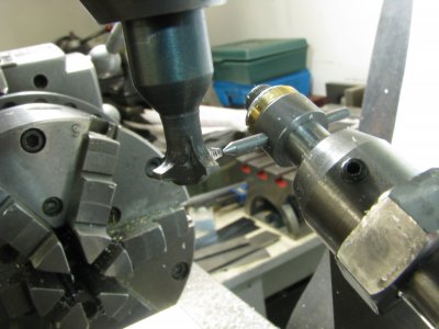
Since Chuck Fellows published the drawings for making and using the helical gear fixture I have made quite a few of them. The problem with the whole setup is the indexing/cutting fixture is always at some angle to cut the required gears. At the cutting end of the mandrel is an arbor to hold whatever blank you're going to be cutting. I have posed the question to machinist friends and thought about it myself but couldn't come up with a reasonably accurate way of centering the cutter both vertically and transversely relative to the centerline of the gear blank.

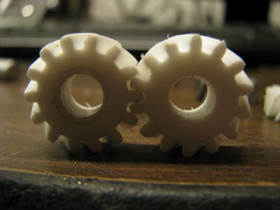
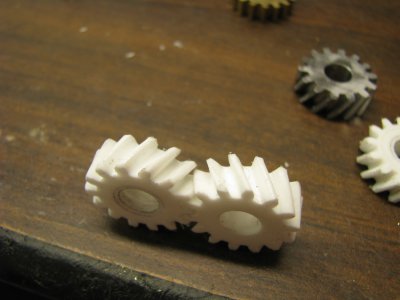
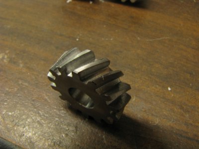
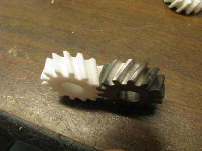
I'm in the process of starting a new project with the completion of the Galion road grader and thought I would like to make another transmission, this one for my flathead engine. My son knows a fellow that has several of them and he offered one to me so that I could take the necessary dimensions. When I built the Borg-Warner T-5 transmission I used spur gears instead of the normal helicals because of the large amount of gear cutting templates required to make all the gears. With this one which has fewer gears I thought I would make the helicals.

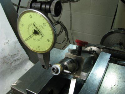
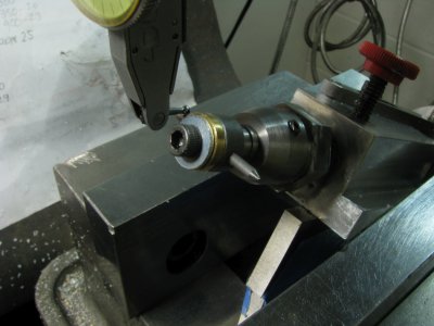
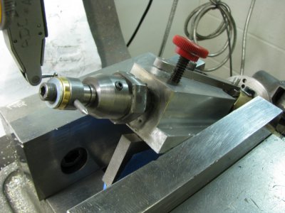
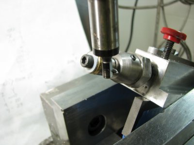
Now back to the problem at hand. The gears will all be .250 wide so I made a setup gauge, if you will, that mounts onto the end of the holding arbor. I started by turning a piece of stock that fits the arbor and is .25 wide, the same as the gears. I cross drilled it .093 diameter and inserted a pin in each side, one with a point and one flat ended. I moved the shaft of the fixture to approximately halfway of it's travel and locked it with the locking screw. The next step is to secure the gauge to the arbor and align it horizontally by eye. I then used the dial indicator to get it completely flat. Step three was to use the edge finder to get to the center of the pin. This was done and -0- set on the readout. (X travel)
 

Attachments

  • IMG_2985.JPG
    IMG_2985.JPG
    474.5 KB · Views: 30
  • IMG_2990.JPG
    IMG_2990.JPG
    427 KB · Views: 29
  • IMG_2991.JPG
    IMG_2991.JPG
    470.1 KB · Views: 26
  • IMG_2995.JPG
    IMG_2995.JPG
    355.2 KB · Views: 27
The home-made gear cutter was secured in the holder and the table (X) was moved to center. The spindle was turned so that the edge of one of the flutes on the cutter was lined up with the point on the gauge. Now the Z was set with a magnifying glass. This is probably the only inaccurate part of the whole setup but for model work it should be very close. This give me the center of travel of the fixture shaft, X position and Z depth, which should be the centerline of the gear blank.
I made some test blanks out of Nylon to test out the setup. The gears are 24 DP, 14 teeth, .660 P.D. and 28 helix angle. A spread sheet was made by Don1966 and it is a great tool when working with gears.
My shaft center spacing is .875 so finding a DP and tooth count for spur gears isn't that big of a problem but when going to helicals the tooth count changes relative to the helix angle. With Don's worksheet you can plug in the variables and keep changing the helix angle until you come up with the proper center spacing. He also expanded on Chuck Fellows contribution by giving the numbers required to create the helical templates.
For a pair of helical gears 2 templates are required, on left hand and one right so this gear box will need 9 templates. Now you see why I didn't go that route with the T-5 trans.
I cut the nylon gears just to verify angles and mesh somewhat then cut one steel gear. I didn't check center spacing but that can be adjusted when I get into making all the steel gears.
 

Attachments

  • IMG_2999.JPG
    IMG_2999.JPG
    405.7 KB · Views: 26
  • IMG_3001.JPG
    IMG_3001.JPG
    331 KB · Views: 22
  • IMG_3002.JPG
    IMG_3002.JPG
    381.5 KB · Views: 22
  • IMG_3003.JPG
    IMG_3003.JPG
    402 KB · Views: 20
  • IMG_3007.JPG
    IMG_3007.JPG
    426 KB · Views: 20
  • IMG_3008.JPG
    IMG_3008.JPG
    506.5 KB · Views: 24
All my helical gear cutting has been done on a #2 Brown & Sharpe universal milling machine, mostly with the horizontal spindle, I line the cutter up visually with a magnifying glass, for the smaller pitches, this is fairly accurate. One thing they suggest is to cut one tooth space, then reverse the blank, having colored it space with layout dye, then re entering the space with the cutter and rotating it by hand and examining the resultant marking; if there is contact at the top of the tooth on one side and at the bottom of the other, a correction is made and another space cut, until the precise correction is made.
After I make the setup with the cutter centered on the tailstock point, I then swing the table to the required spiral angle and commence to cut the teeth. If the spiral angle is too short to swing the table, I use the universal angular attachment to mount the cutter, and the table is swung to suit the spiral angle to match that of the universal head; the setting of the cutter is more problematic in that event. Also coming into play possibly in that situation is that the machine may not be able to cut a lead that short, in that event, the short lead attachment is used.
I have only had to do that once so far, for a pair of timing gears for a one cylinder marine engine; the gears worked at 90 degrees, so the cam shaft was vertical, the ratio was 2:1 as is normal, the gears were the same OD and pitch diameter, the ratio of spiral leads were 4:1; I have yet to completely wrap my head around how that could work, but it did.
 
That's the great thing about working with helical gears. With spur gears you go by the DP and tooth count and that gives you the PD. With those you are limited to the center distance. To change center distance you would have to change gear ratios or DP.
With helical gears of a given DP and tooth count (N) by changing the pitch angle you can change the diameters of the gears and still maintain the center to center spacing. The first time I was introduced to this situation was when I was working on car engines. The camshaft has a helical gear of a given tooth count. The distributor has a helical gear with the same tooth count but it's smaller than the cam gear. How can that be? By changing the pitch angle of the teeth, greater number on one lesser angle on the other the diameters change but the tooth count stays the same.
gbritnell
 
Back
Top