Help diagnosing a broken Hardinge HLV power feed motor.

maxime.levesque

Registered
Registered
Joined
Sep 1, 2023
Messages
68
I recently acquired an HLV with a power feed motor that won't run, and took the time today to diagnose things, and evaluate possible fixes.

From my understanding, the power feed motor is a DC brushed motor, and the DC current produced by the rheostat based controller.

I have disassembled the powerfeed motor, tested the resistance of the two (stator and rotor) coils, and I think I have found the problem: the resistance of the stator coil is way to high.

The measured value is 412 Ohm, so some current can go through it, but most likely not enough to get the motor to move.

I'd first like to confirm that the problem is indeed with the stator coil, my knowledge of electronics is minimal, perhaps there is nothing wrong with 412 Ohm resistance from the stator coil.

I figured it was to high, simply because it is high in comparison to the 31.6 Ohms that I measured from the rotor coil.


I also measured current coming out of the controller (disconnected from the motor) as I rotated the dial, and flipped the high/low switch, and I could make sense of the data collected, and it looked like a functionning controller:

1. flipping the high,low switch made the voltage going to the stator vary from 83v to 198v
2. turning the dial, made the voltage going to the rotor vary from 25v to 179v

So my tests seem to indicate that the controller is working, and the motor broken, apparently as a result of a burned out stator coil.

If the problem is with the stator coil, it seems easy enough to replace, there are only two windings (or poles ?), but I need to make sure I have the right diagnosis.
 
Did you give it the sniff test? It should be obvious that it is a burnout, simply by the acrid smell, also try the resistance of each coil, it may be a clue as to which coil may be defective.
 
There are bridge rectifiers for both armature and stator- I would suspect those first, but yes the stator resistance seems high to me also
Sorry I don't know what the proper value is
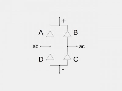
If you disconnect the bridge you can test it with your ohmmeter:
Probe across each of the 4 elements in the bridge with your meter on ohms (Rx1K or autorange, some meters have a diode check)
You should see a low reading or a very high one as you swap the meter probes one way or the other
As a final check probe from + to - you should see the same thing (low reading will be higher than before)
A short across any element or open means the bridge is bad
Diodeoutline.jpeg
 
Last edited:
I would disassemble the motor and look at the condition of that stator. If the coil does not show
signs of overheating, the problem is likely at the wire end connections. That being the case it can
be repaired if the stator is indeed open and you can find the break. While you are at it, it's a good
idea to inspect the brushes for wear. An ohm meter would be helpful in diagnosis.
 
Cathead is where I go except, I would not disassemble the motor until I absolutely had to.
Because I don't know if your voltage readings are (VDC or ACV)if your output voltages are ACV then follow marks diode bridge testing procedure if DCV then I believe your controller is not the issue but that you have damaged or corroded contact to your stator windings and probably accessible without disassembling the motor.
Please post pictures of the data plates on the motor and controller.
 
Not sure about the field resistance but it seams high. From your measurements, the controller seams to be working working properly. They hold the field voltage fixed and vary the armature voltage.

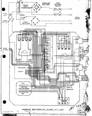
Page 28.jpg
 
Thanks @f350ca, this is exactly the right diagram !

Unfortunately I think I have fried the armature rectifier. I connected it's output to a permanent magnet DC motor to see if it would make the motor turn (stupid idea, I know...), and the only thing that happened is sparks coming out somewhere in the rectifier plate after a few seconds of "nothing" !

I have heard the warnings about the toxic fumes that selenium rectiers can produce when they fry, there was no foul smell, but I did nevertheless turned on a fan, just in case, and left the room.

This is pretty mysterious, because I did a bunch of tests of individual components, all were "passing", but the motor would not rotate.
I will report here the tests results *before* I fried the rectifier:

It turns out that the stator coil might NOT be fried, because, the resistance of each individual coil is the same for both: 204 Ohms.
The combined resistance to the coil pair (they are wired in series) is 412 Ohms.

Here is the data I have collected.

Controller Test Data
  1. Low/High switch: stator voltage is 98v when switch is at high, and 46v when low (it seems like the switch might be inverted, one would think "low" would cause lower voltage, but an inverted low/high switch would still make the motor run).
  2. The "left right" switch causes the rotor voltage go from negative to positive.
  3. The dial resistor causes the voltage to change from 14.1v to 83.8v when turned from low to high (values are negative or positive based on the left/right switch)

So it seems like the controller did what it was supposed to, ... before I fried it...

Motor Test Data
  1. resistance of stator coils (in series): 412 Ohms
  2. resistance of *each individual* stator coils: 204 Ohms
  3. resistance from one rotor brush terminal to the other : 23.4 Ohms
  4. resistance taken from all opposite armature terminal pairs: 18.9 (+/- 0.2 Ohms
  5. resistance taken from all adjacent armature terminal pairs: 3.1 (+/- 0.1) Ohms
  6. current leaks from armature terminal to armature core: none

So from these individual tests, I should have had a running motor, at least in theory !

I'm thinking of ways to test the motor without the controller. I have a bunch of transformers that can produce voltages from 18v, 24v, for computers and other electronic devices.

I would like to hear of some possible test setups before I try to be "creative" and cause further damage !

Could I (for example) connect two separate DC sources, one connected at the brush terminals, and another one at the stator terminals ?
 
Selenium rectifiers have long been superseded by silicon type rectifiers. The silicon ones have no odor of
rotten eggs if they have gone bad.
 
Cat is right, it's high time you replaced the rectifiers anyhow with modern silicon units- they're dirt cheap
Selenium rectifiers can sometimes test ok but fail when loaded; your armature one was probably on the way out
you just "helped" it along with your PM motor test
Bridges rated at a minimum 10 amps at 600 volts should work fine for both locations
Mount them on a metal surface for heatsinking; they don't have fins like selenium units
 
Last edited:
Thanks, I ordered these:

https://www.amazon.ca/gp/product/B07PJ8759Y/ref=ppx_yo_dt_b_asin_title_o00_s00?ie=UTF8&psc=1

I chose them because they could be delivered tomorrow, the specs seem to be the same as those you suggested (hope I didn't miss anything).

I will screw them upside down on a 1" x 4" aluminium plate, 1/2" thick, with fins milled at the back.

Cat is right, it's high time you replaced the rectifiers anyhow with modern silicon units- they're dirt cheap
Selenium rectifiers can sometimes test ok but fail when loaded; your armature one was probably on the way out
you just "helped" it along with your PM motor test
Bridges rated at a minimum 10 amps at 600 volts should work fine for both locations
Mount them on a metal surface for heatsinking; they don't have fins like selenium units
 
Back
Top