Help removing change gear - LMS Hi Torque 7500 (Sieg SC4)

u2fletch

Registered
Registered
Joined
Nov 16, 2023
Messages
25
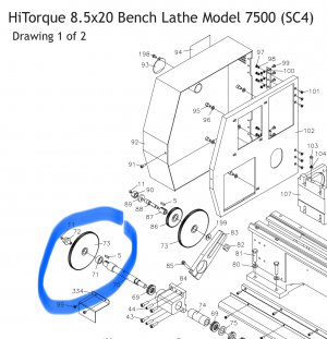
Doing the Claugh42 ELS upgrade on my lathe and would really like to get this gear out of the way. I have a timing pulley which will mount to the 16mm shaft directly below the spindle. The encoder mounts to the right. I can get a much cleaner install if the gear shown here is gone. Have looked in the parts diagram in the manual and the shaft goes through the plate inside the lathe, but it seems there should be a simple way to remove the gear and leave the shaft in place.
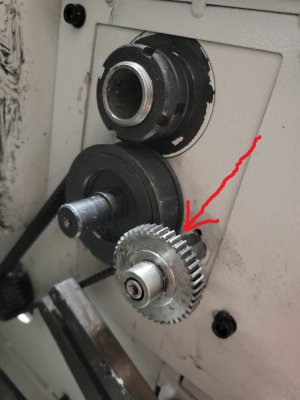
20231125_154901.jpg
 
This gear (#73):

IMG_6279.jpeg
Once the retaining screw is out (as it is in your photo), you should be able to use a puller to break it loose from the shaft.
 
Looking at the diagram, I think you're looking at a gear which is call out number 154, over behind the headstock. Calllout number 153 looks like it should unscrew. You've got some stuff off, I'm wondering about what that taper pin has pinned together And what "appears" to be a collar around callout 153. Is that part of the offending gear, or is that separate? Callout 153, which appears to me to be inside of the piece I'm calling a collar, has flats for a wrench to unscrew it.

Dont' take that to the bank though... I'm just looking at the schematic.

I’ve got you, but the exploded diagram is somewhat confusing: the intermediate shaft (165) mounts in the hole directly below the spindle, but the intermediate shaft retainer (153) is in line with the transition gear (154), not the timing pulley (131).

It looks like the timing pulley drives a transition gear (133), which meshes with the Op’s transition gear (154) on the intermediate shaft which in turn drives the slipping gear (169) meshing with the spindle gear (174). What I can’t see is a shaft for the timing pulley/transition gear. If this is the case, gear 154 can’t be “gone” as it is what powers the spindle.

If the nomenclature is wrong, then the timing pulley drives the intermediate shaft/spindle and the retainer (153) threads into the head stock body (thus the flats) and the OP’s gear drives off the timing pulley to eventually drive the lead screw, which makes more sense. In that case the gear can go away since the ELS stepper will drive the lead screw.

We need another view of the head stock, or better yet @u2fletch needs to give LMS a call.
 
Last edited:
Thanks for your help. Between your two ideas I was able to figure this out. The gear I pointed out is actually gear #154, and it was press fit onto a bearing, #155. The diagram is not real clear, but I used a gear puller to slide it off the bearing. Success!
 
Thanks for your help. Between your two ideas I was able to figure this out. The gear I pointed out is actually gear #154, and it was press fit onto a bearing, #155. The diagram is not real clear, but I used a gear puller to slide it off the bearing. Success!
Great news: as you can see, I finally finished my long-winded reply (switching between pages on a phone is a pain!).
 
I’ve got you, but the exploded diagram is somewhat confusing: the intermediate shaft (165) mounts in the hole directly below the spindle, but the intermediate shaft retainer (153) is in line with the transition gear (154), not the timing pulley (131).

It looks like the timing pulley drives a transition gear (133), which meshes with the Op’s transition gear (154) on the intermediate shaft which in turn drives the slipping gear (169) meshing with the spindle gear (174). What I can’t see is a shaft for the timing pulley/transition gear. If this is the case, gear 154 can’t be “gone” as it is what powers the spindle.

We need another view of the head stock.
Gear 154 is actually an idler gear used in the transfer of power from the spindle to the lead screw. The shaft and gear is labelled “A” in the user manual and threading gear charts. On Page 33 it shows how to swap the gear positions to allow left hand threads.
 
Great news: as you can see, I finally finished my long-winded reply (switching between pages on a phone is a pain!).
I will post a pic of the timing pulley and encoder installation. Need to make one more bushing and it will be ready for assembly. And waiting for perfect sized belt to arrive.
 
Back
Top