

- Joined
- Dec 17, 2020
- Messages
- 56
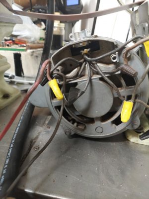
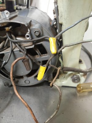
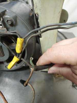
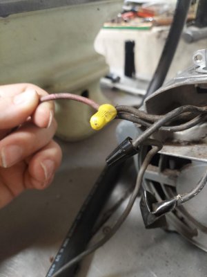
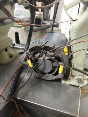
Ok so I need a little help the South bend 9A that followed me home was overhauled not painted (although I should have but no space, I installed a South bend switch and got away from the floppy pole with a switch. I found 1 black wire taped off and the Green wire (Ground or Neutral) coming from the outlet wire, there are 6 black wires coming out of the motor. Also there are multiple wires in the wire nuts some have 3. I just want it wired properly. I wired the barrel switch as it came apart same with outlet plug, I replaced both the 6 conductor wire and the wire to the wall. I used very heavy gauge wire for both (what I could get). I will try to include pics and sorry for the terminology I am no electrician. How is this suppose to be wired correctly? It did run before.
Attachments
-
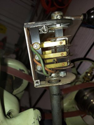 SB 9A switch wire 1.jpg108.8 KB · Views: 17
 -
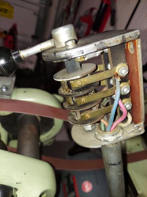 SB 9A switch wire pic 2.jpg119.8 KB · Views: 15
 -
 thumbnail (1).jpg142.9 KB · Views: 14
 -
 thumbnail (2).jpg134.6 KB · Views: 15
 -
 thumbnail (3).jpg134.6 KB · Views: 13
 -
 thumbnail (4).jpg114.5 KB · Views: 13
 -
 thumbnail (5).jpg104.8 KB · Views: 21
 -
 thumbnail (7).jpg99.2 KB · Views: 22
 -
 thumbnail.jpg143.7 KB · Views: 22