Help with Clausing 4903 Magnetic Starter

DNORM25

Registered
Registered
Joined
Mar 16, 2022
Messages
23
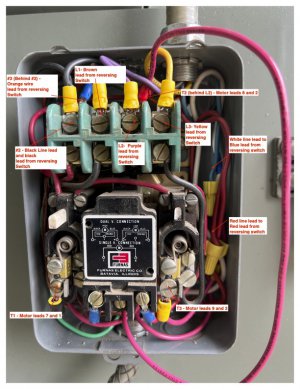
I have a Clausing 4903 with the 7130 magnetic starter option I am having trouble wiring. When I Purchased this lathe it was in pieces, so I was not able to map the disassembly during clean-up and painting.The reversing switch was intact with its wiring connected at the switch, but it, the line voltage and the motor leads were disconnected at the magnetic starter.

I found Clausings wiring diagram for the 7130 starter option, but for a 5910 ( see attached). I connected the line voltage, motor leads and switch per the schematic, but the motor doesn't turn on at the rotary switch, hum or anything. I suspect the previous owner removed a jumper or something at the starter, but I'm not sure and not really familiar with starter wiring. I cannot seem to find any information on the Furnas 14BA32BC internal wiring and the magnetic starter cover was lost long ago so there is no paper label to refer to.

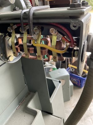
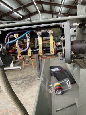
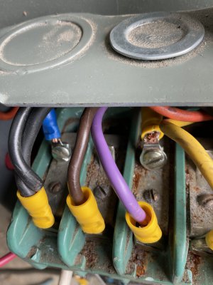
Does anyone have a schematic, suggestion or see something in the attached pictures that looks wrong,I would really appreciate it. This is a three phase motor and I have three phase power connected, so it's not a phase issue.
 

Attachments

  • Clausing W Notes.jpg
    Clausing W Notes.jpg
    147.5 KB · Views: 24
  • Furnas Nameplate.pdf
    1.3 MB · Views: 7
  • Furnas Starter and Switch Wiring.pdf
    1.4 MB · Views: 14
I'm not real familiar with starters but I do see the right side plunger is broken off- it may be that the plungers need to
be pushed by the cover to make it run- don't know
Post a pic of the reversing switch so I can check it- a close shot of the internals
Might be more expedient to just eliminate the starter and use a hefty drum switch
 
Last edited:
Does the contactor pull in when you try to start it? If not, with the power turned off, use an ohmmeter and check for continuity between terminals V and W. This is the starter coil and should read a low resistance. The broken plunger is the right side overload reset. Shouldn't be a problem but will make it harder to reset the overload if it trips. Check resistance through the overload contacts by placing one ohmmeter probe on the terminal with the red wire that's just above and to left of the left reset plunger and the other probe on the terminal above and to the right of the right broken plunger. Resistance should be near zero ohms. If not press each plunger to see if the overloads reset.
 
I'm not real familiar with starters but I do see the right side plunger is broken off- it may be that the plungers need to
be pushed by the cover to make it run- don't know
Post a pic of the reversing switch so I can check it- a close shot of the internals
Might be more expedient to just eliminate the starter and use a hefty drum switch
 

Attachments

  • IMG_0303.jpeg
    IMG_0303.jpeg
    243.7 KB · Views: 9
  • IMG_0302.jpeg
    IMG_0302.jpeg
    270.9 KB · Views: 10
Does the contactor pull in when you try to start it? If not, with the power turned off, use an ohmmeter and check for continuity between terminals V and W. This is the starter coil and should read a low resistance. The broken plunger is the right side overload reset. Shouldn't be a problem but will make it harder to reset the overload if it trips. Check resistance through the overload contacts by placing one ohmmeter probe on the terminal with the red wire that's just above and to left of the left reset plunger and the other probe on the terminal above and to the right of the right broken plunger. Resistance should be near zero ohms. If not press each plunger to see if the overloads reset.
The coil is not pulling in. I assume the red jumper to the right of the reset plunger is what provides line voltage to energize the coil? If so, I would assume this wire should connect to t2 since this appears to feed line voltage outside of the closing of the contacts? Theres no front cover so i am having to guess at the internal wiring using my limited (very limited) knowledge.

With multimeter set to auto range the reading between v and w is .412 k ohms. Reading between overload contacts is 59.1 ohms again with auto range
 
I believe the red jumper wire from to the left of the left plunger should go up to L2. Whare does it go? I think the readings you took look OK. I'm trying to find some info on the coil. I was an industrial electrician for 30 years but I don't remember seeing a coil with a X terminal. Is there a wire on X? Is your supplied voltage 240V? Can you move the armature (movable contacts) up by hand?
 
I believe the red jumper wire from to the left of the left plunger should go up to L2. Whare does it go? I think the readings you took look OK. I'm trying to find some info on the coil. I was an industrial electrician for 30 years but I don't remember seeing a coil with a X terminal. Is there a wire on X? Is your supplied voltage 240V? Can you move the armature (movable contacts) up by hand?
No wires on X. so its set up for low voltage - 240, not 440. the supplied volt is 240. Currently the red wire is going to T2 which is just a tap off L2. Yes the contacts move freel.

Thank you for your help i appreciate it
 
Are you saying L2 and T2 are electrically the same point? Zero ohms between them all the time?
 
Are you saying L2 and T2 are electrically the same point? Zero ohms between them all the time?
Purple wire is attached to L1. T2 is just behind it and not isolated from L1. Continuity between both points.
 

Attachments

  • IMG_0304.jpeg
    IMG_0304.jpeg
    261 KB · Views: 7
Back
Top